


THERMOCOUPLE REPLACEMENT
Step 1. Turn off gas supply to water heater. Rotate knob of combination
thermostat/gas valve to “OFF” position.
Step 2. Remove outer jacket door.
Step 3. Slide open inner combustion chamber door.
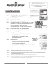
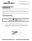
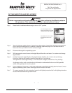
Step 4 Disconnect thermocouple from combination thermostat/gas valve (3/8" wrench). Locate other end of
thermocouple inside of combustion chamber and remove from pilot bracket. Pullfirmly pulling away
from the pilot assembly.
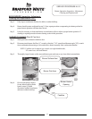
Step 5. Install new thermocouple into pilot bracket making certain the thermocouple is fully engaged into the pilot
bracket. Connect other end of thermocouple to combination thermostat/gas valve (finger tight + ¼ turn).
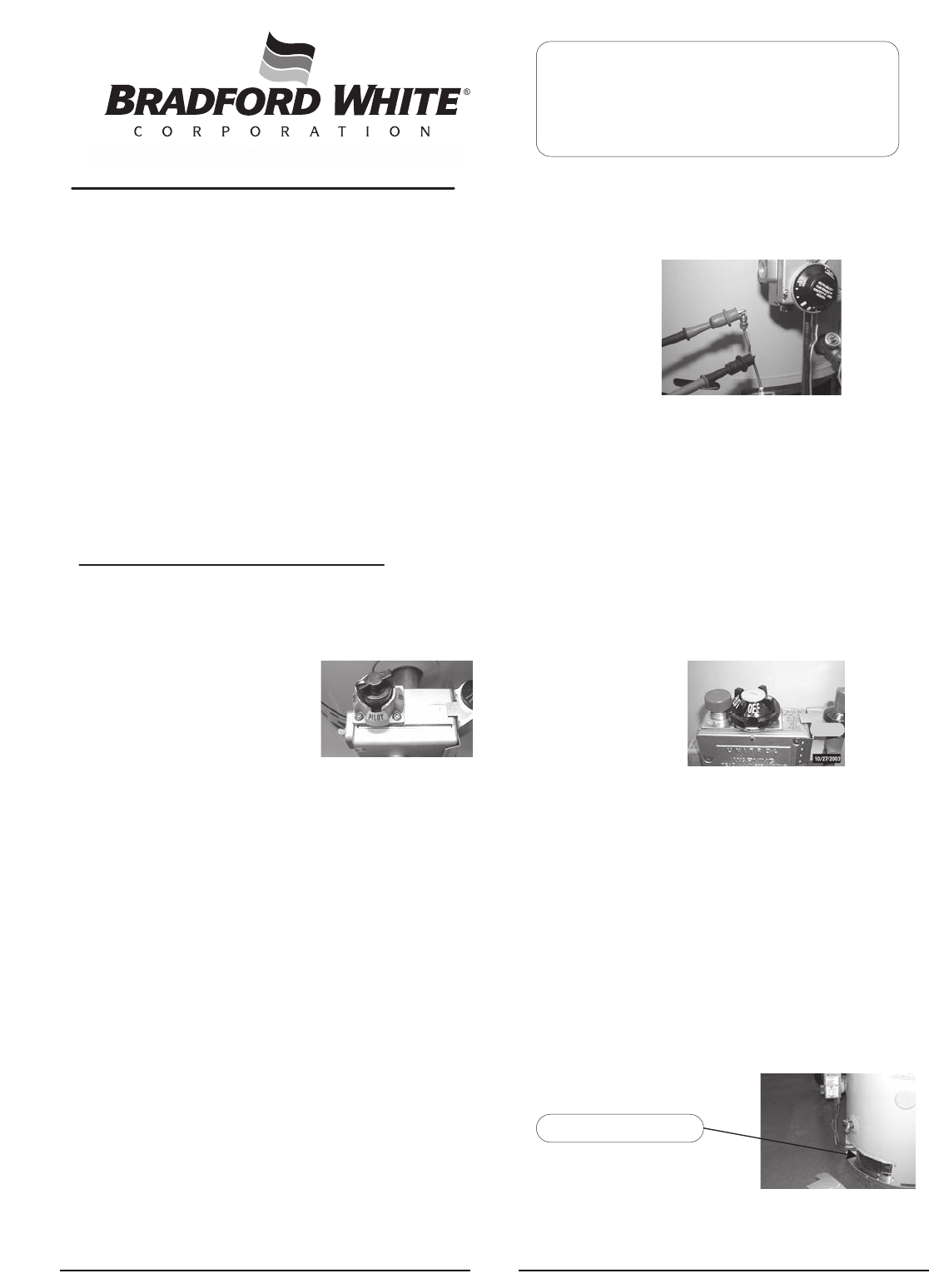
Step 6. Route carefully through the relief opening in the combustion chamber skirt.
Step 7. To resume operation follow the instructions located on the lighting instruction label or the lighting
instructions located in the installation and operation manual.
Step 8. Slide inner door closed when finished.
SERVICE PROCEDURE AG-I
Thermocouple Testing and Replacement
Page 4
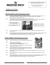
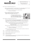
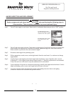
For White Rodgers Control,
depress knob slightly and rotate
clockwise to the “OFF” position.
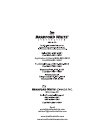
For Robertshaw Control, rotate
knob clockwise to the “OFF”
position.
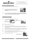
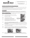
Step 1. Disconnect thermocouple from combination thermostat/gas valve.
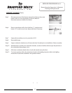
Step 2. Using a multimeter capable of measuring millivolts, connect
one alligator clip to the end ball or contact portion of the
thermocouple, and the other alligator clip to copper portion of
the thermocouple.
Step 3. Following the lighting instruction label on the heater, proceed to light the pilot and allow to operate for
three minutes. It will be necessary to hold the pilot button down continuously throughout this test.
A reading of 20 to 30 millivolts indicates good thermocouple output.
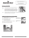
OPEN CIRCUIT THERMOCOUPLE TESTING
Thermocouple position
4