


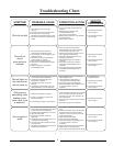
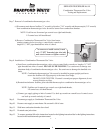

Troubleshooting Chart
SYMPTOM PROBABLE CAUSE CORRECTIVE ACTION
Pilot will not light
1
. No incoming gas or too low gas
pressure.
2
. Gas control knob set to wrong position.
3
. Pilot light button not being fully
d
epressed when attempting to light pilot.
4. Pilot orifice or pilot tube is obstructed or
k
inked.
1. Poor thermocouple connection at
c
ombination thermostat/gas valve.
2. Thermocouple not fully engaged in pilot
assembly bracket.
3. Pilot flame is not fully enveloping the
thermocouple “hot” junction.
4. Weak or defective thermocouple.
5. Open ECO on combination thermostat/
gas valve.
6. Defective magnet in combination
thermostat/gas valve.
Pilot will not
stay lit
when button is
released
Pilot will light, but
the main burner
will not come on
1. Combination thermostat/gas valve set too
low for desired water temperature.
2. Combination thermostat/gas valve
temperature is satisfied.
3. Insufficient gas supply or low gas
pressure.
4. Combination thermostat/gas valve has
wide differential or is out of calibration.
Pilot goes out
periodically (after
heating cycles,
once a day, once
a week etc.)
1. Insufficient combustion air supply.
2. Incorrect, clogged vent system/ vent
terminal or location.
3. Inconsistent gas supply or gas pressure.
Not enough hot
water
1. Combination thermostat/gas valve set too
low for desired water temperature.
2. Cold inlet water temperature is very cold.
3. High demand periods.
4. Incorrectly sized water heater for
application.
5. Combination thermostat/gas valve is out
of calibration/not functioning.
6. Out of spec dip tube is diluting hot water
with cold water.
7. Integrated mixing device is set too low for
desired water temperature.
1. Turn on gas supply and/or check line
pressure.
2
. Review lighting instruction. Set
combination/thermostat
gas valve to correct position.
3. Review lighting instruction. Fully depress
pilot lighting button.
4. Clean, repair or replace.
1
. Check connection at combination
thermostat/gas valve. Proper tightness
should be finger tight plus ¼ turn.
2. Inspect thermocouple to ensure that it is
fully engaged into pilot bracket.
3
. Adjust tip of thermocouple to be fully
engulfed by pilot flame.
4. Check thermocouple and replace if
necessary.
5. Check ECO continuity and replace
combination thermostat/gas valve if
necessary.
6. Check magnet operation and replace
combination thermostat/gas valve if
necessary.
1. Adjust temperature dial on combination
thermostat/gas valve.
2. Check temperature dial setting on
combination thermostat/gas valve.
3. Check gas supply and line pressure.
4. Check combination thermostat/gas valve
for proper operation, replace if
necessary.
1. Verify adequate combustion air is available
to the unit. Check and clear Jacket slot
openings of any dirt, dust, restrictions or
other obstructions.
2. Check venting for proper sizing and proper
operation
3. Check gas supply and line pressure.
1. Check dial on combination thermostat/gas
valve.
2.Extremely cold water going into the heater
will decrease the amount of hot water
produced. It may be necessary to temper
incoming water supply.
3. Adjust high demand usage.
4. Contact Plumbing professional.
5. Check combination thermostat/gas valve
for proper operation, replace if
necessary.
6. Inspect dip tube and replace if necessary.
7. Reset device using the procedure
in the instructions included with the device.
SERVICE
PROCEDURE
1
. See Service Procedure
AG-III, Page 6.
4
. See Service Procedure
AG-II, Page 5.
4. See Service Procedure
AG-I, Page 4
5. See Service Procedure
AG-III, Page 6
6. See Service Procedure
AG-III, Page 6
2. See Installation &
operation manual.
3. See Service Procedure
AG-III, Page 6
4. See Service Procedure
AG-III, Page 6
3. See Service Procedure
AG-III, Page 6
5. See Service Procedure
AG-III, Page 6
6. See Service Procedure
AG-V, Page 13
Page 3
3