


Brute Deluxe (200, 300, 400)
Page 25
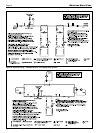
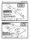
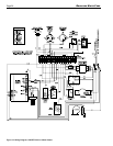
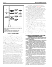
Figure 14. Field Wiring.
5.2 Field Wiring
Field Installed Pump: A pump contactor can be
wired to the “2” and “4” terminals on the pump time
delay relay, attached to dry contacts of an adjustable
delay. The contacts may be used to switch a larger
pump contactor or can be used to directly switch the
hot leg of a circulator pump, up to 1 hp at 120 VAC or
3/4 hp at 240 VAC.
Note that in some cases, the pump is run
continuously by switching the pump status switch
position to "constant".
Note terminals “2” and “4” are located on the
time delay relay, which is mounted to the bottom of
the control panel tray and accessed when the tray is
swiveled to the "up" position.
To connect the pump, crimp the two spade
connectors to the black (hot) and white (neutral) pump
wires (as shown in pump diagram, Figure 14). The
other end of the pump wired needs to be connected
to the boiler's 110V legs using the existing wire nuts
(located in the transformer cover box). Also note
the transformer cover box is removed by lifting the
retaining tab (on the left side of the box) up and out of
the retaining slot, and sliding the box to the left until it
stops, before raising it straight up.
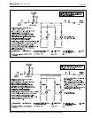
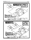
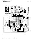
Other Field Interlocks: To install other eld-
wired switches (proving switches, ow switches, etc.),
remove the jumper between the terminals labeled “3”
and “4” (see Figure 13)