


Brute Deluxe (200, 300, 400)
Page 13
1. Detailed instructions for the installation of the
venting system design or the venting system
components; and
2. A complete parts list for the venting system
design or venting system.
(d) MANUFACTURER REQUIREMENTS
– GAS EQUIPMENT VENTING SYSTEM
NOT PROVIDED. When the manufacturer
of a Product Approved side wall horizontally
vented gas fueled equipment does not
provide the parts for venting the fuel gases,
but identies “special venting systems”, the
following requirements shall be satised by
the manufacturer:
1. The referenced “special venting system”
instructions shall be included with the appliance
or equipment installation instructions; and
2. The “special venting systems” shall be Product
Approved by the Board, and the instructions for
that system shall include a parts list and detailed
installation instructions.
(e) A copy of all installation instructions for all
Product Approved side wall horizontally
vented gas fueled equipment, all venting
instructions, all parts lists for venting
instructions, and/or all venting design
instructions shall remain with the appliance
or equipment at the completion of the
installation.
2.3.2 Side Wall Combustion Air Terminal
The Bradford White side wall combustion air
terminal (listed in Table 1) must be used when the
unit takes its combustion air through a duct from a
side wall. Consider the following when installing the
terminal:
1. Do not locate the air inlet terminal near a source
of corrosive chemical fumes (e.g., cleaning uid,
chlorinated compounds, etc.)
2. Locate the terminal so that it will not be subject
to damage by accident or vandalism.
3. Locate the combustion air terminal so that it
cannot be blocked by snow. The National Fuel
Gas Code requires that it be at least 12 inches (30
cm) above grade, but the installer may determine
it should be higher, depending upon local
conditions.
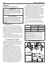
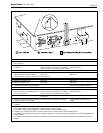
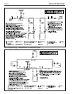
4. If the Brute Deluxe is side-wall vented to the
same wall, locate the vent terminal at least 3
feet (0.9m) horizontally from the combustion air
terminal, and locate the vent terminal at least 1
foot (0.3m) above the combustion air terminal
(see Figure 3).
2.3.3 Vertical Vent Terminal
When the unit is vented through the roof, the
vent must extend at least 3 feet (0.9m) above the point
at which it penetrates the roof. It must extend at least
2 feet (0.6m) higher than any portion of a building
within a horizontal distance of 10 feet (3.0m), and high
enough above the roof line to prevent blockage from
snow. When the combustion air is taken from the roof,
the combustion air must terminate at least 12" (30cm)
below the vent terminal (see Figure 2).
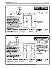
2.3.4 Vertical Combustion Air Terminal
When combustion air is taken from the roof, a
eld-supplied rain cap or an elbow arrangement must
be used to prevent entry of rain water (see Figure 2).
The opening on the end of the terminal must be at least
12" (30cm) above the point at which it penetrates the
roof, and high enough above the roof line to prevent
blockage from snow. When the vent terminates on the
roof, the combustion air must terminate at least 12"
(30cm) below the vent terminal.
2.4 Common Vent Test — Boilers
When an existing boiler is removed from a
common venting system, the common venting system
is likely to be too large for proper venting of the
appliances remaining connected to it.
At the time of removal of an existing boiler, the
following steps shall be followed with each appliance
remaining connected to the common venting system
placed in operation, while the other appliances
remaining connected to the common venting system
are not in operation.
1. Seal any unused openings in the common venting
system.
2. Visually inspect the venting system for proper
size and horizontal pitch and determine there is
non blockage or restriction, leakage, corrosion
and other deciencies which could cause an
unsafe condition.
3. Insofar as it is practical, close all building doors
and windows and all doors between the space in
which the appliances remaining connected to the
common venting system are located and other
spaces of the building. Turn on clothes dryers
and any appliance not connected to the common
venting system. Turn on any exhaust fans, such
as range hoods and bathroom exhausts, so they
will operate at maximum speed. Do not operate a
summer exhaust fan. Close replace dampers.
4. Place in operation the appliance being
inspected. Follow the lighting instructions.
Adjust thermostat so appliance will operate
continuously.
5. Test for spillage at the draft hood relief opening
after 5 minutes of main burner operation. Use
the ame of a match or candle, or smoke from a
cigarette, cigar or pipe.
6. After it has been determined that each appliance