


Internet Version for Reference Only
BRADFORD WHITE
Page 4
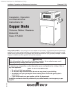
Copper Brute B4 Volume Water Heaters
Page 5
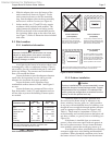
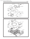
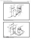
e. Slide the adapter plate over the bottom of the
stack extension as shown in Figure 5. Fit the
stack extension down over the ue transition
ring. Seat the adapter plate on the top assembly
and secure it with two screws (see Figure 6).
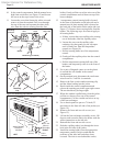
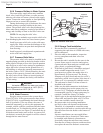
f. Indoor models, size 175 and 250 only, require
an adapter cable (included with product). The
cable connects the blocked vent safety switch
(BVSS) on the bell of the external draft hood to
the 6-position Molex plug on the side of the unit
(see Figure 7). Refer to instruction sheet included
with cable.
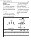
2.3 Site Location
2.3.1 Installation Information
WARNING
Improper installation or maintenance can cause
nausea or asphyxiation from carbon monoxide
in ue gases which could result in severe injury,
property damage, or death.
Avoid placing the heater in locations where it can
be damaged by water or condensate leakage. If this is
not possible, provide a suitable drain pan to catch and
divert any leakage. The pan must not block natural
ow of air around the heater.
Locate the heater to provide adequate clearance
on all sides for inspection, service and to provide
adequate air circulation for proper operation.
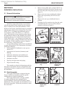
Locate the heater so the clearances from
combustible surfaces shown in Table 1 and Figure 8
are met.
Locate the heater on a waterproof oor with a
oor drain and a 6 inch (152 mm) minimum curb on
all four sides to protect the building if heater repairs
are needed.
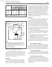
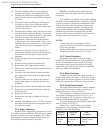
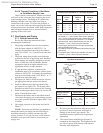
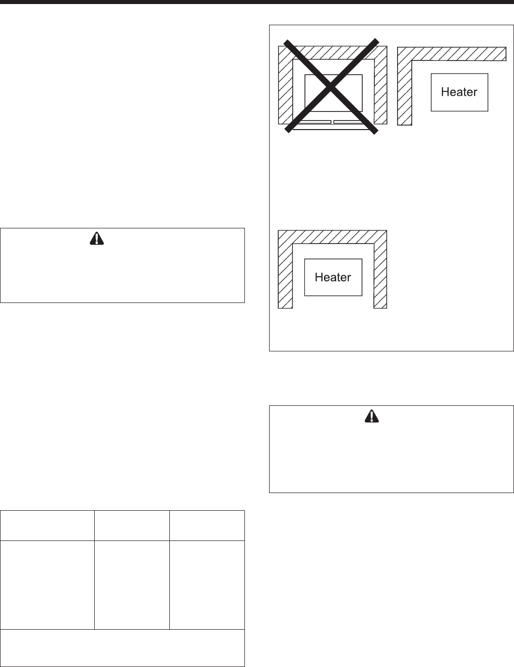
Figure 8. Alcove installation.
Closet Installation
(unacceptable)
A closet is any 4 sided enclosure
which is less than 16* times the
total volume of all the gas red ap-
pliances within the enclosure.
Room Installation
(acceptable)
A room is any enclosure which is
at least 16* times greater than the
total volume of all the gas red ap-
pliances within the enclosure
Alcove Installation
(acceptable)
An alcove suitable for the installa-
tion of a heater is a restricted sec-
tion of a room not separated from
the room by a door or partition and
which meets the minimum clear-
ances specied in this manual.
* When the ceiling height exceeds 8 feet, you are only allowed to con-
sider 8 feet when calculating the total volume of the enclosure.
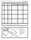
Indoors Outdoors
Clearance from: inch mm inch mm
Top 37 940 Unobstructed
Water conn. side 12 305 Unobstructed
Opposite side 6 152 6 152
Front Alcove Unobstructed
Rear 6 152 6 152
Vent* 6 152 —
Flooring Combustible Combustible
Service clearance = 36 inches (914mm) at front of heater,
and 18 inches (457mm) at water connection side.
*1" (25mm) if double wall vent is used.
Table 1. Minimum Boiler Clearances
from Combustible Surfaces.
2.3.2 Outdoor Installation
Caution
Outdoor installations are not recommended in areas
where the danger of snow blockage exists. Copper
Brute heaters can be installed in the standard low-
prole, grate top conguration as received from the
factory, or with an optional vent cap.
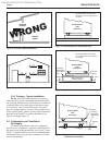
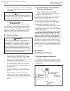
Locate the heater in an open, unroofed area.
Do not locate the heater below or adjacent to any
doors, windows, louvers, grills, etc., which connect
in any way with an inhabited area of a building, even
though the access might be through another structure
such as a garage or utility room (see Figure 9 and
Table 1). There must be a minimum of 4 feet (1.22
m) horizontally and vertically between the heater and
any door, window, or gravity inlet to a building (see
Figure 10).
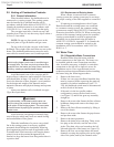
If the heater is installed close to a structure,
protect it from rain water runoff with rain gutters on
the roof or other measures. Do not locate the heater
near sprinkler systems that could spray water on it.
Avoid locations where wind deection off nearby
structures might cause wind loading and downdraft
conditions. Where downdraft conditions exist, locate
the heater at least 3 feet (0.91 m) from the structure.