


Internet Version for Reference Only
BRADFORD WHITE
Page 12
Copper Brute B4 Volume Water Heaters
Page 13
To
Drain
Heater
T1
A
B
Remote
Temperature
Control for Heater
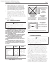
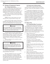
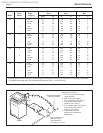
Heat Flow Pressure* Water Temp
Exch. Water Rate Drop Rise
Model Passes Category
gpm L/s ft. m °F °C
175 2 Soft 22 1.4 5.8 1.8 13 7
Normal 34 2.1 11.2 3.4 8 4
Hard 46 2.9 19.1 5.8 6 3
4 Soft 11 0.7 4.9 1.5 25 14
Normal 17 1.1 9.3 2.8 16 9
Hard 23 1.5 15.9 4.8 12 7
250 2 Soft 22 1.4 5.8 1.8 18 10
Normal 34 2.1 11.2 3.4 12 7
Hard 46 2.9 19.1 5.8 9 5
4 Soft 11 0.7 4.9 1.5 35 19
Normal 17 1.1 9.3 2.8 33 18
Hard 23 1.5 15.9 4.8 17 9
325 2 Soft 34 2.1 12.5 3.8 18 10
Normal 34 2.1 12.5 3.8 18 10
Hard 46 2.9 21.7 6.6 11 6
4 Soft 17 0.7 10.4 3.2 36 20
Normal 17 0.7 10.4 3.2 30 17
Hard 23 1.5 18.1 5.5 22 12
400 2 Soft 34 2.1 13.3 4.1 19 11
Normal 34 2.1 13.3 4.1 19 11
Hard 46 2.9 23.4 7.1 14 8
4 Soft 17 0.7 11.1 3.4 37 21
Normal 17 0.7 11.1 3.4 37 21
Hard 23 1.5 19.5 5.9 27 15
*Pressure drop includes head loss of heat exchanger and through 30 feet (9.1 m) of pipe and normal ttings when heater
is installed with storage tank. Pipe and ttings are assumed to be 1-1/2 inch (38 mm).
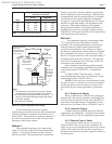
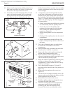
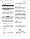
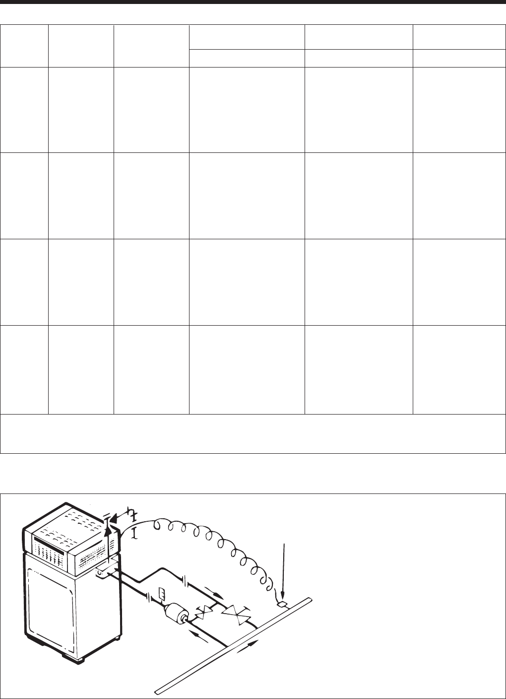
Main Circulating Loop
(With Own Pump)
Water Maintained
Less Than 110°F (43°C)
Adjustment Procedure
1. Turn on heater and open gate
valves A and B.
2. After 15 minutes, read T1.
3. If T1 is less than 110°F (43°C),
slowly close valve B until T1
climbs to 110°F (43°C).
4. If T1
is greater than 110°F (43°C),
slowly close valve A until T1
drops to 110°F (43°C).
5. Check after 5 minutes
operation and make nal
adjustments.
Figure 20. Cold water application.
Table 4. Pump Performance Requirements.