


Internet Version for Reference Only
BRADFORD WHITE
Page 28
Copper Brute B4 Volume Water Heaters
Page 29
2. If the voltmeter reads voltage, the safety fuse and
the fusible link are good.
3. Replace the fusible link when an open circuit is
detected. An open fuse line indicates overheating
in the ue collector or compartment.
4. Check for leaks of the ue collector, vent pipe,
gaskets, and all connections.
5. Check the ue pipe for blockage.
6. Check heat exchanger ns for partial sooting.
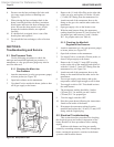
5.2.7 Testing the Fuse
To test the fuse:
1. Clip a lead of the voltmeter to the grounding
terminal.
2. Touch the other voltmeter lead to the 24VAC
terminal on the ignition control.
3. If there is no voltage, replace the fuse. A blown
fuse is usually an indication of a short in the
24VAC circuit. It is important that the cause of
the short be found and repaired. Do not jumper or
bypass the fuse.
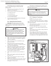
5.2.8 Testing the Ignition Control
(for spark ignition)
Caution
The ignition control and igniter operate on 120V
power. Keep this in mind while servicing the heater,
and take care to avoid electrical shock.
The ignition control provides power to the pilot,
opens the gas valve when there is a call for heat, and
senses when a ame is established. To test the ignition
control for spark ignition:
1. Clip one lead from the voltmeter to the yellow
wire terminal on the transformer.
2. Touch the other voltmeter lead to the red 24V
terminal on the ignition control.
3. If the voltmeter reads voltage, the temperature
control and the manual reset hi-limit switch are
not keeping the heater from ring.
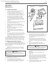
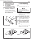
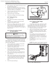
4. Make sure the pilot burner is positioned next to
the main burner (see Figure 40) and there is no
soot or dirt on it.
5. Make sure the electrode (part of pilot assembly)
is clean, the terminal connection is tight, and the
ceramic insulator lead is at least 3/8 inch (9.5
mm) from the heater chassis and other metal
parts.
6. Check for proper spark gap.
Figure 40. Pilot location (spark ignition).
5.2.9 Testing the High Voltage
Ignition Lead
Connections must be tight, and silicone rubber
boots in place. Bare metal parts at the base of the
manifold bracket must be at least 3/8 inch (9.5 mm)
from other metal objects. To test the ignition lead:
1. Turn the control panel switch to on.
2. Make sure the temperature control is turned far
enough to call for heat. There will be a loud
clicking noise indicating the pilot electrode is
sparking.
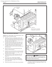
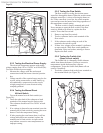
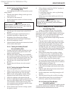
3. If no sparking is heard, pull the ignition lead
from the ignition control and hold the bare
terminal 1/8 to 3/16 inch (3.2 to 4.8 mm) from
the ignition stud with a pair of insulated pliers
(see Figure 41).
4. If a spark does not jump the gap, replace the
ignition control.
NOTE: The ignition control cannot be repaired
in the eld. If it does not operate properly, replace it.
Figure 41. High voltage ignition test.