


Internet Version for Reference Only
Installation continued-
MINIMUM CLEARANCES
WARNING
Failure to adhere to these installation and operating instructions
may create a hazard to life and property and will nullify the
warranty.
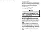
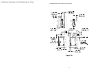
This installation shall allow access to the front of the water heater and
adequate clearance shall be provided for servicing and operating this
water heater. The water heater may be installed on either a combustible or
non-combustible floor. If the water heater is to be installed directly on
carpeting, it shall be installed on top of a metal or wood panel extending
beyond the full width and depth of the appliance by at least three (3) inches
(7.6 cm) in any direction or, if the appliance is to be installed in an alcove or
closet, the entire floor shall be covered by the panel. The minimum
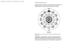
clearances to combustibles for this water heater is: zero (0) inch (0 cm) from
the sides and rear, four (4) inches (10.2 cm) from the front of the jacket, zero
(0) inch (0 cm) from the plenum, zero (0) inch (0 cm) from the air intake
elbow and telescopic tubes and twelve (12) inches (30.5 cm) from the direct
vent-air intake terminal. (See Figure 1). Refer to figure 1B for front to back
dimensions of the water heater for installations in a closet.
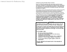
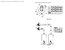
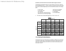
When two direct vent water heaters are installed in a closet and the
installation situation requires the vent terminals to be vertically aligned, then
the clearances between the vent terminals must be a minimum of 9” for the
50 gallon model and 12” for the 65 and 75 gallon models. Refer to figure 2.
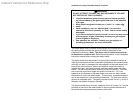
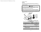
OPTIONAL DIRECT VENT-AIR INTAKE TERMINAL GUARD
WARNING
The direct vent-air intake terminal is HOT while the water heater is
in operation. Do not touch. Keep children, combustibles, gasoline
and other liquids having flammable vapors away.
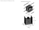
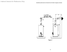
It is recommended that a vent-air intake terminal guard be installed when the
vent-air intake terminal is located where it can be touched accidentally, or
accessed by children. (See Figure 3).
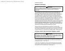
A chain link or louvered fence may be used instead of the vent-air intake
terminal guard. Maintain proper clearances as specified in this instruction
manual to the vent-air intake terminal. (See Figure 4).
8