


Internet Version for Reference Only
Installation (Vent-Air Intake System Installation) continued-
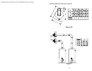
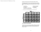
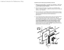
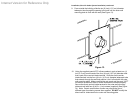
1. Measure the vertical height “Y” required in your installation. (See Figure
7). Reference the appropriate Table A to determine number of vent-air
intake kits required in your installation.
2. Measure the horizontal length “X” required in your installation (See
Figure 7). Reference Table A to determine number of vent-air intake kits
required in your installation.
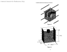
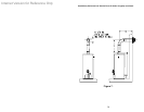
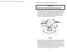
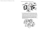
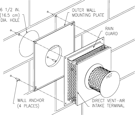
3. Cut a 6-1/2 inch (16.5 cm) diameter minimum clearance hole in the wall
at the point where the vent-air intake tubes will pass through the outside
wall and connect with the direct vent-air intake terminal
(See Figure 8).
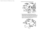
4. From outside the building, position the outer wall mount plate and direct
vent-air intake terminal over the center of the opening. Mark the
mounting screw hole locations. With a 3/16 inch (4.7 mm) diameter drill
bit (not supplied), drill holes for the wall anchors (supplied). Install the
wall anchors but DO NOT affix the outer wall mount plate and direct
vent-air intake terminal to the wall at this time (See Figure 8). Note:
Certain construction of walls may require the use of a different type of
wall anchoring means than supplied. DO NOT modify the direct vent-air
intake terminal or outer wall mount plate.
Figure 8.
18