


Internet Version for Reference Only
Installation continued-
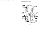
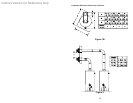
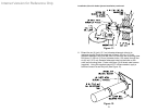
VENT-AIR INTAKE SYSTEM INSTALLATION
WARNING
The vent-air intake system must be properly installed. Failure to
properly install the vent-air intake system could result in property
damage, personal injury or death.
Do not install any damaged vent-air intake system components.
Contact the manufacturer of the water heater for replacement parts.
IMPORTANT
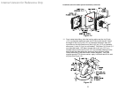
When the following instructions specify, to seal a vent-air intake joint,
use only Loctite Ultra Blue 587 RTV Silicone sealant. A tube of Loctite
Ultra Blue 587 RTV Silicone sealant is supplied with each optional vent-
air intake kit. Make sure that all joints are completely sealed.
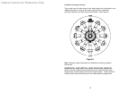
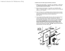
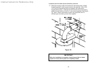
When drilling pilot holes for the #8 sheet metal screws through the six
(6) inch (15.2 cm) diameter components, be careful not to drill into the
inner four (4) inch (10.2 cm) diameter components.
WARNING
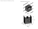
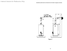
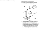
The vent-air intake terminal must be installed through at outside wall in
a horizontal position. This direct vent water heater is not designed for
through the roof vertical venting.
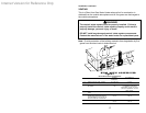
Tools Required For Vent-Air Intake Installation
The following minimum tools are required to properly install the vent-
air intake system. Note: Wall construction will determine tool usage.
Tape Measure
Drill
3/16 inch (4.75 mm) Diameter Drill Bit(s)
1/8 inch Diameter (3.2 mm) Drill Bit(s)
Masonry Drill Bit(s) (For Poured Concrete, Concrete Block and Brick Wall
Construction)
Reciprocating Saw w/appropriate Blade(s) (Dependent on Wall
Construction)
Chisel (For Poured Concrete, Concrete Block and Brick Wall
Construction)
Hammer (For Poured Concrete, Concrete Block and Brick Wall
Construction)
1/4 & 5/16 inch Nut Drivers (Preferred) or Slotted Head Screwdriver
Phillips Head Screwdriver
17