


20 6 720 606 599
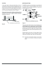
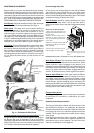
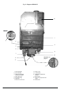
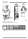
Fig. 15 - Diagram of WR430-7K
1. Heat exchanger
2. Pilot assembly
3. Burner manifold gas
pressure test nipple
4. Main gas burner
5. Pilot gas tubing
6. Gas valve
7. Electronic control box
5
11
1
4
9
10
12
2
6
8
7
13
3
See fig 7,
page 13
See table 1 on
page 15
8. Power cord
9. on/off switch
10. Temperature adjustment
selector
11. Microswitch
12. Gas inlet gas pressure test
nipple
13. Exhaust Fan