


16 6 720 606 599
Do not enlarge the orifice.
Do not use any wire or sharp object to clean orifices. Natural
gas orifices are large enough that you can usually clean
them by blowing through them. To access the pilot orifice,
remove 2 screws holding pilot assembly in place. Then loosen
compression fittings to expose pilot orifice.
Heat Exchanger should be visually examined once a year
or more often in dusty areas. If fins at top show dust or
debris accumulation, remove and clean with brush and soapy
water.
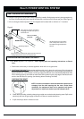
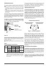
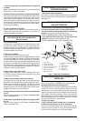
Fig. 12 - Characteristic Pilot Flame
To clean the pilot burner and/or the pilot orifice: Turn off
the gas to the unit. Set the On/Off switch to Off (position
). Remove the cover of the heater. To do so, pull off the
temperature adjustment knob and unscrew and remove the
plastic collar. Pull main cover out toward you and lift up and
out. The pilot orifice should be cleaned or replaced.
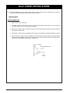
Main Burner Flames: The main burner flames should be
blue, with a more intense blue cone in the center core. Yellow
flames could be a sign of plugged or dirty burners, or a
blockage on the heat exchangers fins. If some burners have
yellow flames while others have good flames, it is likely that
dust, lint or spider webs have partially clogged the burner
venturis. To clean the burners, contact a gas service person.
Mineral Scale Build-up: In hard water areas the Bosch,
when operated at lower temperature settings, tend not to
accumulate mineral buildup. If however, the heater is used
at the higher temperature settings and the water has a high
mineral content, periodic descaling may be necessary. The
heating coil should be removed and flushed with a descaling
solution. Signs of scaling are rising outlet temperature and
knocking noises when water is flowing.
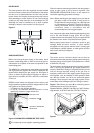
Flue gas safety device:
The flue gas safety device must not under any circumstances
be switched off, simulated or replaced by any other
component.
Operation and safety precautions
The flue gas safety device checks the effectiveness of flue
gas extraction by the flue. If it is inadequate, the appliance
switches off automatically so that the combustion fumes do
not escape into the room in which the appliance has been
installed. The flue gas safety device resets after a cooling-
down period.
If the appliance shuts down while in operation, ventilate the
room. Wait about 10 minutes then restart the appliance. If
the problem recurs, call an engineer. The user must never
make any modifications to the appliance.
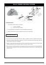
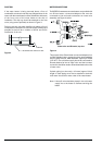
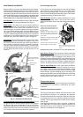
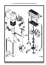
Removal of the Heat Exchanger
1. Shut off the gas and water cold
supply lines to the heater and remove
the front cover.
2. Remove the drain screw from the
bottom of the water regulator and
open the hot water tap to allow the
unit to drain.
3. Remove cover and unscrew metal
retaining bar at the top front of the
heat exchanger
4. Undo water connection nuts at
heat exchanger from both sides
5. Tilt the heating body to the front
at the top and lift away from the
heater.
Estimated service time is 10 minutes to re & re, plus cleaning time
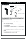
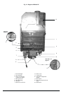
MAINTENANCE AND SERVICE
Approximately once a year, the Bosch should be checked,
cleaned and serviced as necessary. To remove the front cover,
first remove the incandescent particle tray, then pull off the
temperature adjustment knob and unscrew and remove the
plastic collar. Pull main cover out toward you and lift up and
out. THE FOLLOWING OPERATIONS SHOULD BE
PERFORMED BY A QUALIFIED SERVICE PERSON:
Vent System: Should be checked annually. Clean and repair
as needed. See Preventative Maintenance Page 11.
Water Valve: The water valve on this heater should be
serviced periodically. The frequency will depend on the
mineral content of the water and conditions of use or
whenever signs of corrosion appear at the gas and water
valve joint. Check that the water inlet filter (#36 on Figure
18, page 20) is clean. Diaphragm should be replaced every
7-8 yrs. in residential applications and 3-5 yrs for commercial
applications. In acid water areas the venturi should also be
replaced at the same time (#30 on Figure 17, page 21).
Pilot Flame: The pilot flame should burn with a clean, sharp,
blue flame and should resemble the diagram in Fig. 12. If
the flame is soft and yellow the pilot screen may be dirty or
the pilot burner orifice may need to be cleaned or replaced.
The pilot flame should be approximately 2 inches long,
extending past the flame sensor. If the flame is too small, it
will not reach the flame sensor and the burners will not
come on.
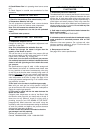
3mm
Correct gap between
pilot burner tip and
electrode tip
Sparking plug
electrode
Flame sensor
Sparking
plug
electrode
Pilot cap orifice
Pilot tube