


20
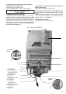
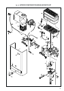
Fig. 18
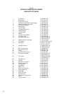
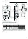
INTERIOR COMPONENTS DIAGRAM
AND PARTS LIST WR430
1 Front Cover 8 705 421 255
2 Bosch Decal 8 701 103 050
3 Plastic lower snap-on 8 705 506 451
4 Temperature adjustment knob complete 8 702 000 219
5 Temperature adjustment knob 8 702 000 111
6 Exhaust fan assembly 8 707 204 023
7 Draft diverter 8 705 505 451
8 Fan protection 8 701 302 164
9 Flue gas safety device 8 707 206 185
10 Heat Exchanger 8 705 406 235
11 Hot water pipe 8 700 705 556
12 Washer 8 710 103 045
13 Overheat sensor (ECO) 8 707 206 040
14 Cold water pipe 8 700 705 294
15 Main burner assembly 8 708 120 298 NG
8 708 120 296 LP
16 Washer for burner assembly 8 710 103 060
17 Throttle disc 8 700 100 189 LP only
18 Gas Valve 8 707 011 811 NG
8 707 011 812 LP
19 Diaphragm switch 8 708 504 021 NG
8 708 504 049 LP
20 Main solenoid valve 8 708 501 250
21 Pilot solenoid valve 8 708 501 249
22 O-ring 8 700 205 120
23 Electrode ignition group 8 718 107 067
24 Pilot burner assembly 8 708 105 337 NG
8 708 105 491 LP
25 Pilot orifice 8 708 200 069 NG
8 708 200 312 LP
26 Pilot gas tube 8 700 707 349
27 Washer 8 700 103 173
28 Electronic control box 8 707 207 011
29 Electric control box 8 707 101 021
30 On/Off switch 8 707 200 014
31 Microswitch 8 707 200 007
32 Water valve 8 707 002 534
33 Water valve repair kit 8 703 406 178
34 Slow ignition valve 8 708 503 063
35 Diaphragm 8 700 503 053
36 Water inlet filter 8 700 507 045
37 Selector screw 8 708 500 251
38 Volumetric water governor 8 707 402 015
39 Venturi 8 708 205 249
40 Cover complete 8 705 500 076