


EN
|
9
Bosch Security Systems | 15 March 2004
5INSTALLATIO N
5.1 General
Code Merger units are supplied in an indoor rated
enclosure designed to fit a standard EIA 19" rack.
Install the unit in the rack using appropriate mounting
hardware (not supplied).
Input connections to a Code Merger are made to any
of its 9-pin D-type connectors. The pinouts of the
supplied 2-meter (6 feet) data cables can be connected
directly to the control code output connector of an
Allegiant Series Matrix Switcher system. Remember to
tighten all connector attachment screws at each
connection point.
If the control code sources are beyond the length of
the cable, or are not Allegiant systems, the data cables
must be adapted as necessary, for connection to the
control device. If desired, a user-supplied 9-pin D-type
connector may be used for interfacing to the Code
Mergers. Pinouts for the 9-pin connectors are
described within this manual.
Connect shielded twisted pair cable (Belden 8760 or
equivalent) between the camera site receiver/driver
locations, and any of the 32/64 outputs provided on
the rear panel of the Code Merger unit. The same data
is generated from all outputs, thus it is irrelevant which
one is used.
Eight (8) pairs of removable screw terminal blocks are
provided, each having four (4) connection groups per
block. Typically, a single camera site receiver/driver or
AutoDome is connected to each output, but the
biphase output of these units is rated to handle up to
eight (8) devices, when connected in a daisy chain
configuration, to a maximum of 1.5 km (5000 ft).
In a daisy chain connection, the cable is looped
through each AutoDome camera or receiver/driver
along the way. Only the last unit in the daisy chain
connection must be terminated. The remaining
receiver/drivers must have the terminating resistor
removed when the looping cable is connected.
Select and maintain a wire color convention to avoid
confusion at the various camera sites.
Example: White to "+", Black to "-", and Shield to "S".
Follow the standard installation instructions, provided
with the AutoDome Camera or Allegiant Series
Receiver/Driver unit, for setting device address and
connecting the data cable to the unit.
Connect the AC power cord to an appropriate power
source. The green Power LED on the code merger
unit front panel should illuminate when power is
applied.
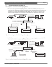
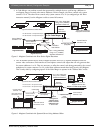
5.2 Camera Address Offset Feature
(effective May 2003, Date Code 0314)
Code Merger units contain an optional feature that can
be used to offset the camera addresses for data being
received by code merger inputs 2, 3, and 4. Input 2
can be set to offset addresses by 16, input 3 by an
offset of 32, and/or input 4 by an offset of 48. This
feature allows code mergers to be used in multi-device
systems where some of the control devices do not
support offset camera addresses of the data being
generated. Refer to sample configuration diagrams for
additional details.
The cover of the Code Merger must be removed to
access the dip switch used for configuration of options.
Follow the instructions below to set the camera address
offset.
LTC 8569 Series | Instruction Manual | Installation