


LTC 8569 | Instruction Manual | Pinouts
EN
|
13
Bosch Security Systems | 15 March 2004
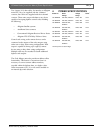
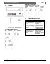
8 Pinouts
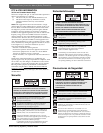
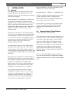
Figure 7 - Code Merger Connectors
12-Pin Output Data Connectors
Pin
1
Connection Pin Connection
1 + Data + 7 + Data +
2 S Shield 8 S Shield
3 - Data - 9 - Data -
4 + Data + 10 + Data +
5 S Shield 11 S Shield
6 - Data - 12 - Data -
1. Pins are not numbered; numbers represent pin sequence from top
to bottom.
9-Pin Data Input Connectors
Pin Connection
1 + Code
2 -- Code
3 Shield
4 No Connection
5 No Connection
6 No Connection
7 No Connection
8 No Connection
9 No Connection
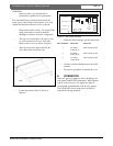
Supplied 9-Pin Data Cables
(Replacement part number 303 0753 005)
Male side Connection Female side Typical Wire
Color (actual color
may vary)
1 + Code 1 Brown
2 - Code 2 Red
3 Shield 3 Orange
4 Gnd 4 Yellow
5 Gnd 5 Green
6 No Connection — ————
7 No Connection — ————
8 12VAC 8 White
9 12VAC 9 Black
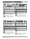
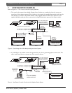
9TROUBLESHOOTING
CODE
POWER
LTC 8569 Series: 8 12-Pin Connectors
LTC 8571 Series: 16 12-Pin Connectors
LTC 8569/60 Series and LTC 8571/60 Series: 2 D-Connect
LTC 8570/60 Series and LTC 8572/60 Series: 4 D-Connect
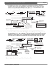
12345
6789
+
S
–
+
S
–
+
S
–
+
S
–
CODE IN 1 CODE IN 2
CODE IN 3 CODE IN 4
Problem
Front panel POWER LED
is not lit.
No front panel CODE LED
action when data is being
received.
No apparent control code
being generated at one
output.
Solution
Check AC power
connections.
Check data input polarity
connections at both the
Code Merger input and
controller device output.
Swap output connections
to another output.
Note: All outputs generate
the same data.