


EN
|
10
Bosch Security Systems | 15 March 2004
WARN ING:
•Removal of the cover should only be
performed by qualified service personnel.
The unit should always be disconnected from the
mains power source before removing the cover, and
remain disconnected while the cover is removed.
• Electrostatic-sensitive device. Use proper ESD
safety precautions to avoid electrostatic
discharge to sensitive electronic components.
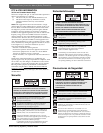
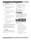
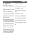
• The top cover is fastened to the case by four
(4) screws located on the rear of the unit.
Remove these screws as shown in Figure 1.
• After the screws have been removed, the
cover slides back and off the unit.
Figure 1 - Cover and Rack Brackets Removal
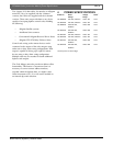
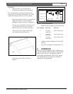
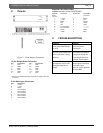
• Locate dip switch # S101, as shown in
Figure 2.
Figure 2 - Dip Switch Location
• Make the desired changes per the table below:
S101 Dip Switch Switch OFF Switch ON
2 No change Data received by Input
2 offset by 16
3 No change Data received by Input
3 offset by 32
4 No change Data received by Input
4 offset by 48
•All other switches should be left in the OFF
position.
•Reverse the procedure to reinstall the cover.
6OPERATION
When AC power is applied to the Code Merger, the
front panel POWER LED illuminates. When biphase
code is received at any of its inputs, the signal is
reconstituted and distributed from all of its outputs.
The CODE LED on the front panel will flash as
output data is being produced.
LTC 8569 Series | Instruction Manual | Operation
Rear Panel board
Main board
Dip Switch S101
Front Panel
ON