6 720 608 782
Installation instructions
13
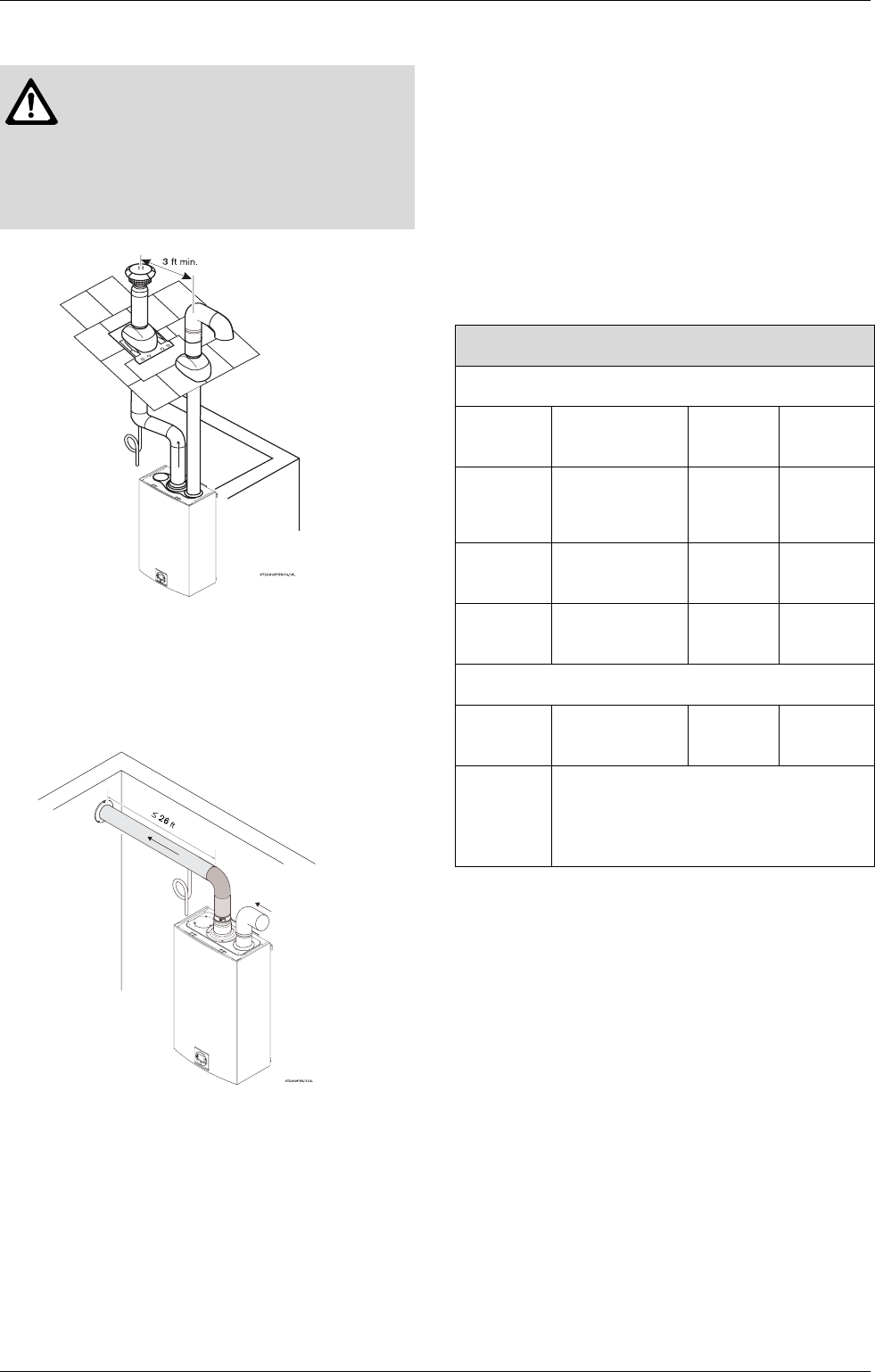
Fig. 18
Open combustion installation (SINGLE PIPE
SYSTEM)
Not recommended in cold climate areas, see
chapter 3.4, page 15.
Fig. 19
Connecting a one piece 90 degree elbow pipe to the
combustion air inlet adaptor is required. This will
prevent debris or objects from falling into the appliance.
The exhaust vent system must vent directly to the
outside of the building and an adequate amount of
indoor combustion air must be provided for this
installation. See chapter 3.4.
Note: reduce 2.5 ft for each 90° elbow used after the
first one, reduce 1.25 ft for each 45° elbow.
A maximum of three 90-degree elbows are permitted.
Determining installation adjustment
The GWH 2400 ES comes factory set to accomodate
most common venting arrangements. Determine the
elbows and straight pipe you will require for exhaust and
combustion air. Refer to the the table below to deter-
mine if the factory setting for the fan is adequate. If your
venting system is longer and exceeds the values listed
in Table 8, proceed to Section 6.7, page 33 for fan
speed adjustment.
Note: Maximum of three 90° elbows allowed for exhaust
and three 90° elbows allowed for intake.
Warning: Approved terminators must
be used for inlet and exhaust vent
systems to prevent rain from entering
the appliance, failure to do so may result
in damage to the appliance. This failure
is not covered under the manufacturer’s
warranty.
TWIN PIPE
Exhaust
Intake
One 90° elbow
or Less (feet)
Two 90°
elbows
Three 90°
elbows
1 x 90°
elbow or
Less
19’ 16.5’ 14’
2 x 90°
elbow
16.5’ 14’ 11.5’
3 x 90°
elbow
14’ 11.5’ 9’
SINGLE PIPE
No intake
piping
19’ 16.5’ 14’
Maximum combined intake and exhaust
vent length without
fan speed
adjustment.
Table 8


