


6 720 607 909
26
Installation instructions
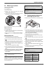
B If the CO
2
content is too high, use the next smallest
restrictor.
B After replacing the restrictor, measure CO
2
level
again. Repeat procedure until correct level is
obtained.
B Once correct reading is obtained, replace screw with
gasket in exhaust collar.
B Press On/Off button to turn heater Off and exit
Service Mode.
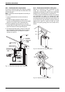
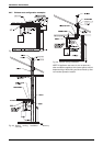
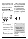
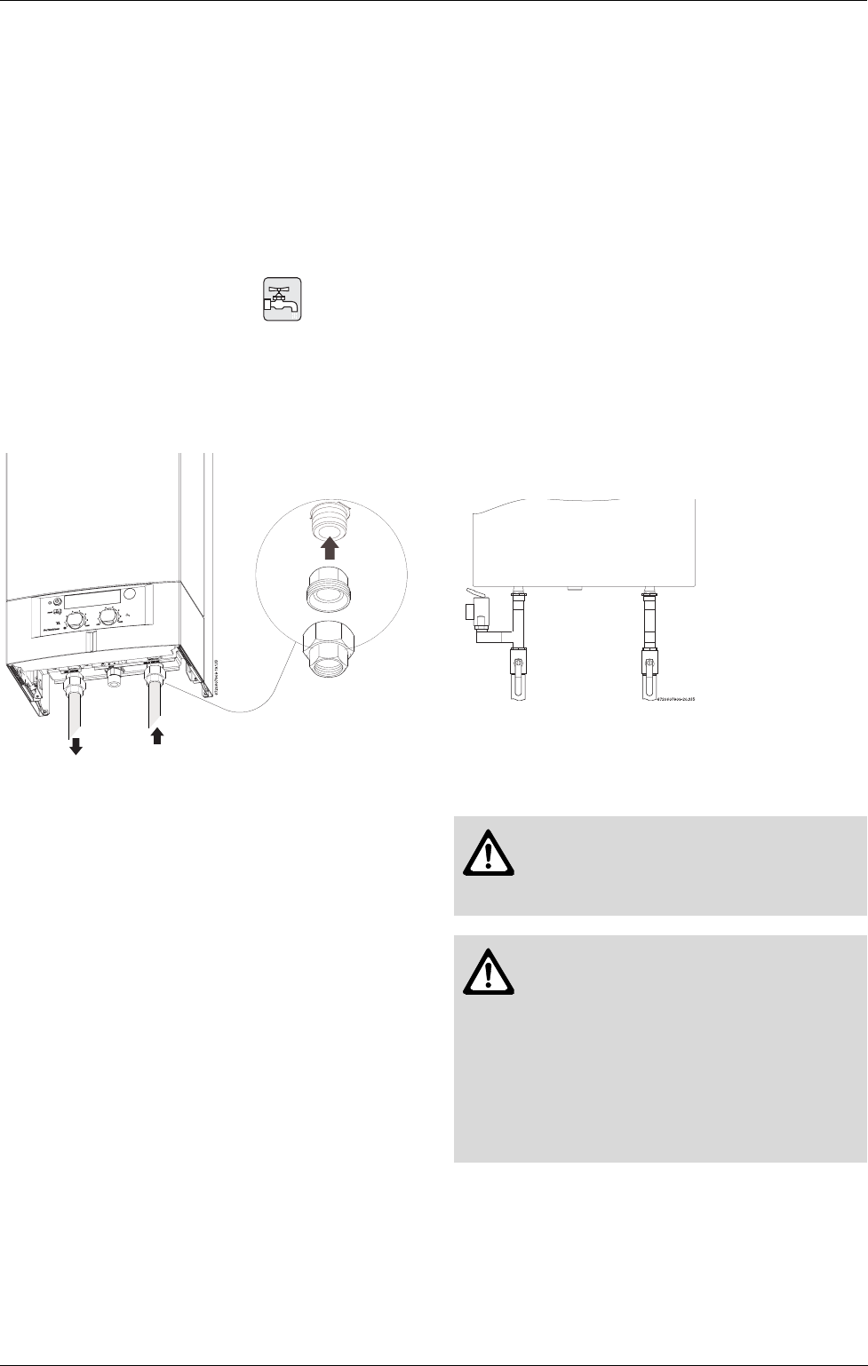
3.10 Water connections
B When facing the heater, the ¾” NPT inlet is on the
bottom right and the ¾” NPT outlet is on the bottom
left (Fig. 29). Install the heater centrally in the build-
ing if possible and make piping runs as short as pos-
sible.
Fig. 29
B The use of unions when connecting both water pipes
to the inlet and outlet connections is recommended.
This will facilitate any necessary servicing.
B Although water piping throughout the building may
be other than copper, we recommend that copper or
suitably rated stainless steel flex line piping be used
for the water connections for 3’ on either side of the
recirculating water heater (follow local codes if more
stringent).
B Never sweat any rigid piping directly to or beneath
the water connections, damage can occur to the
internal heater components during the sweating
process.
B Plastics or other PEX type plumbing line materials
are not suitable for connecting directly to the water
heater.
B Keep water inlet and outlet pipes to no less than ¾"
(19.05mm) diameter to allow the full flow capacity.
B If the cold and hot connections to the heater are
reversed, the heater will not function correctly. Be
certain there are no loose particles or dirt in the
piping. Blow out or flush the lines before connecting
to the water heater.
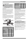
B Full port shut off valves should be installed on both
the cold water supply and hot water outlet lines to
facilitate servicing the heater (see Fig. 30).
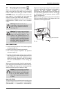
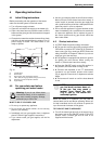
Connecting the pressure relief valve (PRV)
The listed pressure relief valve supplied with the heater
must be installed at the time of installation. No valve is
to be placed between the PRV and the heater. No
reducing coupling or other restriction may be installed
in the discharge line. The discharge line must be a
minimum of 4” above a drain and installed such that it
allows complete drainage of both the PRV and the line.
The location of the PRV must be readily accessible for
servicing or replacement, and be mounted as close to
the water heater as possible. See Fig. 30. To install the
PRV, a suitable fitting connected to an extension on a
“T” fitting can be sweated to the hot water line.
Support all piping.
Fig. 30 Plumbing Connections and Pressure Relief
Valve
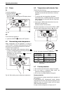
3.11 Electrical connections
The GWH-345/450-ESR requires an electrical power
supply from a 120VAC 60Hz circuit and must be
properly grounded.
A means for switching off the 120VAC power supply
must be provided.
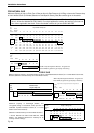
The heater is wired as shown in the wiring diagram
(chapter 4.8, Fig. 35).
OUTLET INLET
Warning: For safety reasons,
disconnect the power supply to the
heater before any service or testing is
performed.
Warning: This heater must be
electrically grounded in accordance
with the most recent edition of the
National Electrical Code. NFPA 70. In
Canada, all electrical wiring to the
heater must be in accordance with local
codes and the Canadian Electrical
Code, CSA C22.1 Part 1. Do not rely
on the gas or water piping to ground the
metal parts of the heater.