6 720 607 909
Installation instructions
25
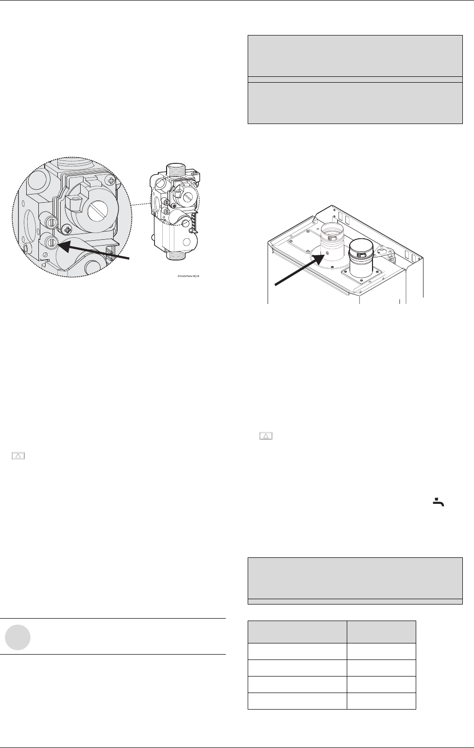
3.8 Measuring gas pressure
Connecting manometer
B Turn power off.
B Shut off gas supply.
B Remove front cover and locate the inlet gas
measuring point (see Fig. 27).
B Loosen screw inside test point fitting (do not remove)
and connect manometer tube on test point.
Fig. 27 Gas pressure measuring (lower tapping)
Static pressure test
B Turn gas supply on.
B Operate all other gas appliances on same gas piping
system at maximum output.
B Keep unit off and record static pressure reading in
Table 11.
Operating pressure test
B Press On/Off button to turn heater On.
For this test the unit has to be put in Service Level
B After 10 seconds, press and hold the reset button
.
B Rotate the recirculating water temperature selector
(left knob) to the minimum and then to maximum.
B Release the reset button and the display should
show * (blinking).
The unit has now entered Service Mode.
B Place a demand for heat by turning external tank ther-
mostat control to maximum for unit to fire at maximum
input.
B Record operating pressure reading in Table 11.
B Press On/Off button to turn heater Off and exit
Service Mode.
Operating gas pressures lower than 5.5" W.C. for nat-
ural gas or 11" W.C. for LP will result in improper oper-
ation and must be corrected. See Chapter 3.7 for gas
line sizing requirements.
3.9 Checking restrictor plate size by
measuring CO
2
level value.
B Remove brass flat head screw on the exhaust collar.
Fig. 28 Measuring port
B Insert CO
2
analyzer probe into the measuring point.
The tip of the probe should be in the center of the flue
pipe. Avoid air gaps between probe and measuring
port to avoid inaccurate readings.
B Press On/Off button to turn heater On.
For this test the unit has to be put in Service Level.
B Open a hot water tap.
B After 10 seconds, press and hold the reset button
.
B Rotate the recirculating water temperature selector
(left knob) to the minimum and then to maximum.
B Release the reset button and the display should
show * (blinking).
B Rotate the hot water temperature selector to the
maximum.
B The restrictor size is correct if the CO
2
level is within
the values as per table 13.
i
Note: after verification tighten the screw
inside the test point.
Static Gas Pressure Reading (see Chapter 3.8)
enter here: ___________________
Operating Gas Pressure Reading (see Chapter 3.8)
enter here: ___________________
Table 11
CO2 value (%)
enter here: ___________________
Table 12
Appliance CO
2
(%)
GWH-345-ESR-N 6.8 - 7.2
GWH-345-ESR-L 7.5 - 8.0
GWH-450-ESR-N 6.5 - 7.0
GWH-450-ESR-L 7.0 - 7.5
Table 13 CO
2
levels at max. input


