


6 720 607 909
Installation instructions
17
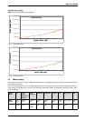
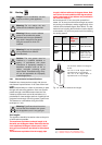
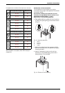
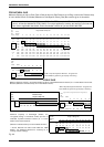
Use table below to define which restrictor to be used.
After installation is complete, check CO
2
levels per
chapter 3.9.
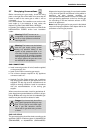
Combustion air inlet connection
The combustion air inlet accessory can only be
connected to the top right of the appliance. The left side
must remain sealed.
Note: Before installing the combustion air inlet
accessory, the appropriate inlet air restrictor must
be determined using Tables 6, 7 and 8.
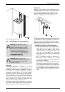
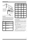
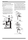
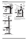
Refer to Fig. 15 for mounting sequence.
B Place gasket, deflector, gasket and inlet air restrictor
on the air inlet opening lining up screw holes as seen
in Fig. 15.
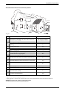
Fig. 15 Mounting sequence
a Gasket
b Deflector
c Restrictor
d Adaptor
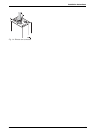
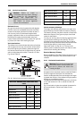
B Attach the combustion air inlet accessory (8 705
504 141) to the top of the unit (position 3) using the
4 screws provided.
B Install 3" combustion air pipe over the air inlet
accessory. If using flexible piping, secure with a
clamp (position 4, not included).
Fig. 16 Exhaust air inlet accessory
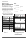
Total equivalent length (ft) Restrictor Ø
GWH345
NG
20 - 38 38
38 - 78 40
GWH450 NG
18 - 28 44
28 - 40 47
40 - 65 50
65 - 78 55
Total equivalent length (ft) Restrictor Ø
GWH345
LPG
20 - 38 38
38 - 78 40
GWH450 LPG
18 - 28 47
28 - 50 50
50 - 78 55
Table 8 Restrictors table