


F220 Series Detectors with F220-B6RS Bases Install the Bases | en 19
Bosch Security Systems, Inc. Installation Manual F.01U.029.847 | -01 | 2007.02
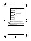
The alarm loop relay (Form A, Terminals 1 and 2) and the power
supervision relay (Terminal 3 and 4) are rated for 0.5 A at
120 VAC/DC for resistive loads.
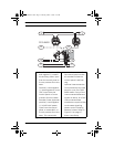
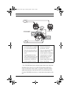
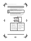
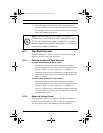
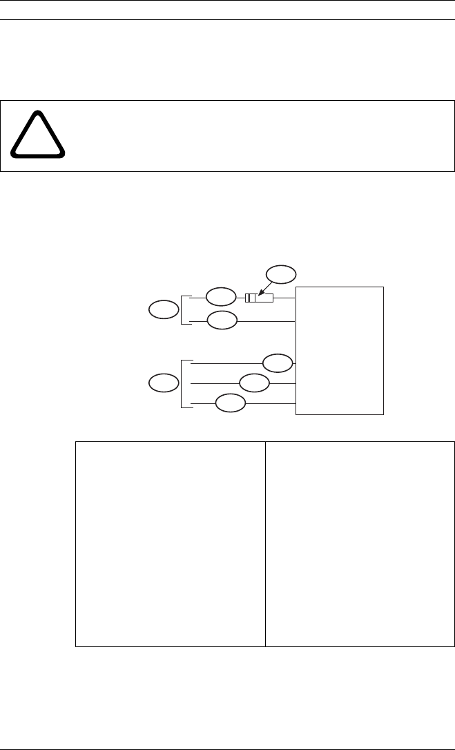
3.5.2 Wire D275 Power Supervision Module
When a D275 Module is used with 24 VDC systems, connect the
yellow wire to the output terminal (b1 or b2). The red wire
remains unconnected (refer to Figure 3.5 on page 19).
!
CAUTION! Do not connect relays to inductive or
capacitive loads. Use with resistive loads only.
1. EOL resistor (refer to the
control panel’s
installation instructions
for specifications).
2. The positive (+) and
negative (-) IDC wires
(blue) from the D275.
3. Connect the positive (+)
IDC wire through the EOL
resistor to Terminal 2 and
the negative (-) IDC wire
to Terminal 1 on the last
base on the loop.
4. Red wire is not used.
5. Yellow wire to Terminal b1
on last base on loop for
24 VDC systems.
6. Black wire (common) to
Terminal a1/a2 on last
base on loop.
7. Power loop
F ig. 3.5 Wiring a D275 Power Supervision Module as a Loop Terminator
4
7
1
2
2
3
6
5
Common (-)
+24 VDC
+12 VDC
D275
F01U029847-01.book Page 19 Thursday, March 1, 2007 9:27 AM