


12 en | Install the Bases F220 Series Detectors with F220-B6RS Bases
F.01U.029.847 | -01 | 2007.02 Installation Manual Bosch Security Systems, Inc.
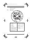
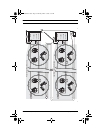
3.4.1 NAC Configurations
In these configurations, the sounders are controlled and
powered from the control panel’s NAC power circuit or a
remote NAC power circuit. The positive (+) wire from the NAC
or D132B Multi-use Reversing Relay Module connects to
Terminal 5 and the negative (-) wire connects to Terminal 4
(refer to Figure 3.2, Item 3 on page 14). The sounders on the
loop follow the NAC configuration programmed at the control
panel. The DIP switches (refer to Figure 2.1, Item 15 on page 4)
are set as shown in Table 3.1.
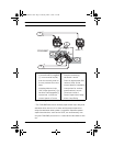
– NAC Follower (Direct Wire) Configuration: The sounders
on the loop follow the signal on the NAC terminals as pro-
grammed at the control panel. Refer to the control panel's
installation manual for NAC configuration instructions. This
configuration requires an extra pair of supervised wires for
the sounder circuit (refer to Figure 3.2, Item 3 on page 14).
– Reverse Polarity Configuration: Tthe sounders in a loop
activate due to reversed polarity on the power line. The
output pattern is not controlled by the base in this operat-
ing mode; it follows the signal on the head terminals as
programmed at the controlpanel.
!
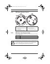
WARNING! DIP switches 1 and 2 must be either both on
or both off. Having one on and the other off could result
in incorrect operation including failure to alarm.
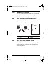
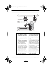
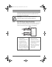
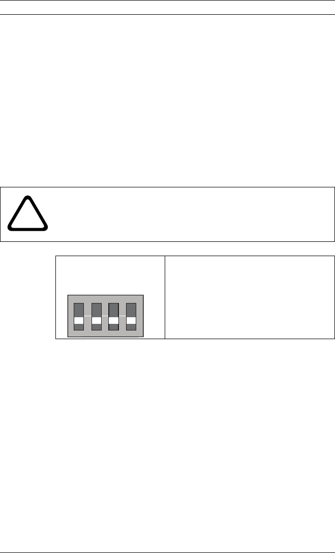
Position 1 and 2 off;
3 and 4 either both on
or both off.
Control panel NAC circuit power is
applied to the base to Terminals 4(+)
and 5(-). The sounder follows the
configuration of the NAC. The
positions of switches 3 and 4 have no
affect.
Table 3.1 NAC Configuration DIP Switch Settings
O N D I P
1234
F01U029847-01.book Page 12 Thursday, March 1, 2007 9:27 AM