


DX4010i | Installation Instructions | 5.0 DX4010i Jumper Pin Settings
6 Bosch Security Systems, Inc. | 1/05 | 4998141106C
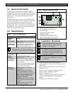
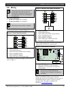
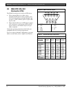
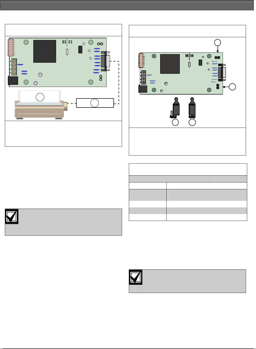
Figure 5: Parallel Device Connections
SER
RxTx
BUS
RxTx
LED
ENABLE
DB9 GND
ENABLE
P1
P6
P2
P3
2
1
1- Parallel converter cable box (BlackBox P/N:
PI045A
2- Parallel printer (compatible option bus control
panels only)
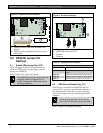
5.0 DX4010i Jumper Pin
Settings
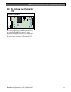
5.1 Enable LED Jumper Pins (P2)
Use the diagnostic LEDs for troubleshooting. To
enable the LEDs, place a jumper plug across the
jumper pins labeled P2.
Refer to Figure 6 for jumper pin settings.
The DX4010i draws more current when the
diagnostic LEDs are enabled. Do not
enable the diagnostic LEDs under normal
operating conditions.
Figure 6: P2 Jumper Settings
4 3
2
SE R
RxTx
BUS
RxTx
LED
ENABLE
DB9 GND
ENABLE
P1
P6
P2
P3
1
1- Diagnostic LED enable pins (P2)
2- DB9 GND enable pins (P1)
3- Enabled
4- Disabled
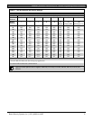
Table 2: Diagnostic LED Functions
Diagnostic LED Function
BUS RX
Data bus receives data from control
panel
BUS TX
Data bus transmits data to control panel
SER RX
RS-232 receives data from serial device
SER TX
RS-232 transmits data to serial device
5.2 DB9 Ground Enable Pins (P1)
Some devices connected to the DB9 DTE RS-232
connector (P6) can cause a ground fault condition on
the control panel. If this occurs, removing the plug
across the P1 jumper pins can clear the ground fault
condition.
Some devices might still cause a ground
fault even if the P1 jumper plug is removed.
Refer to Figure 6 for jumper pin settings.