


DX4010i | Installation Instructions | 1.0 General Information
4 Bosch Security Systems, Inc. | 1/05 | 4998141106C
1.0 General Information
The DX4010i is a data terminal equipment (DTE)
configured RS-232 serial device interface (SDI) module
designed to operate with compatible control panels. It
connects to the control panel through the option or
SDI data bus.
The DX4010i is used to connect a PC with RPS, BIS,
PC 9000, CMS 7000, or other third party software that
uses a serial conncetion to the supported control
panels. The module also supports a serial printer (or
parallel printer with a convertor box) for control panels
that support a serial printer. The compatibility lists in
Table 1 show support information.
2.0 Specifications
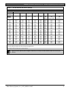
Table 1: DX4010i Specifications
Operating
Voltage
12 VDC
Current Draw
50 mA nominal, 55 mA with diagnostic
LEDs enabled
Communication
Configuration
Programmable through the control
panel. Refer to the appropriate control
panel programming instructions.
The baud rate for the printer output on a
DS7400Xi must be greater than 300 baud.
Operating
Temperature
0°C to +50°C (+32°F to +122°F)
Relative
Humidity
5 to 85% @ +30°C (+86°F)
non-condensing
Control Panel
Compatibility
Option bus control panels: D6412,
D4412, DS7240, DS7220, DS7400Xi
(v2.02 or higher)
SDI bus control panels (v6.0 or higher):
D9412G, D7412G, D7212G, D9124,
D9112, D7412, and D7212
Application
Compatibility
RPS: supported on all compatible
control panels
PC 9000: supported on SDI Bus
control panels (D9412G, D7412G,
D7212G, D9112, D7412, and D7212)
BIS: supported on SDI Bus control
panels, v6.3 and higher (D9412G,
D7412G, and D7212G)
CMS 7000: supported on DS7400Xi
Control Panels set at Mode 18 (v3.09
or higher)
Printers: supported on compatible
Option Bus control panel
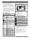
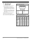
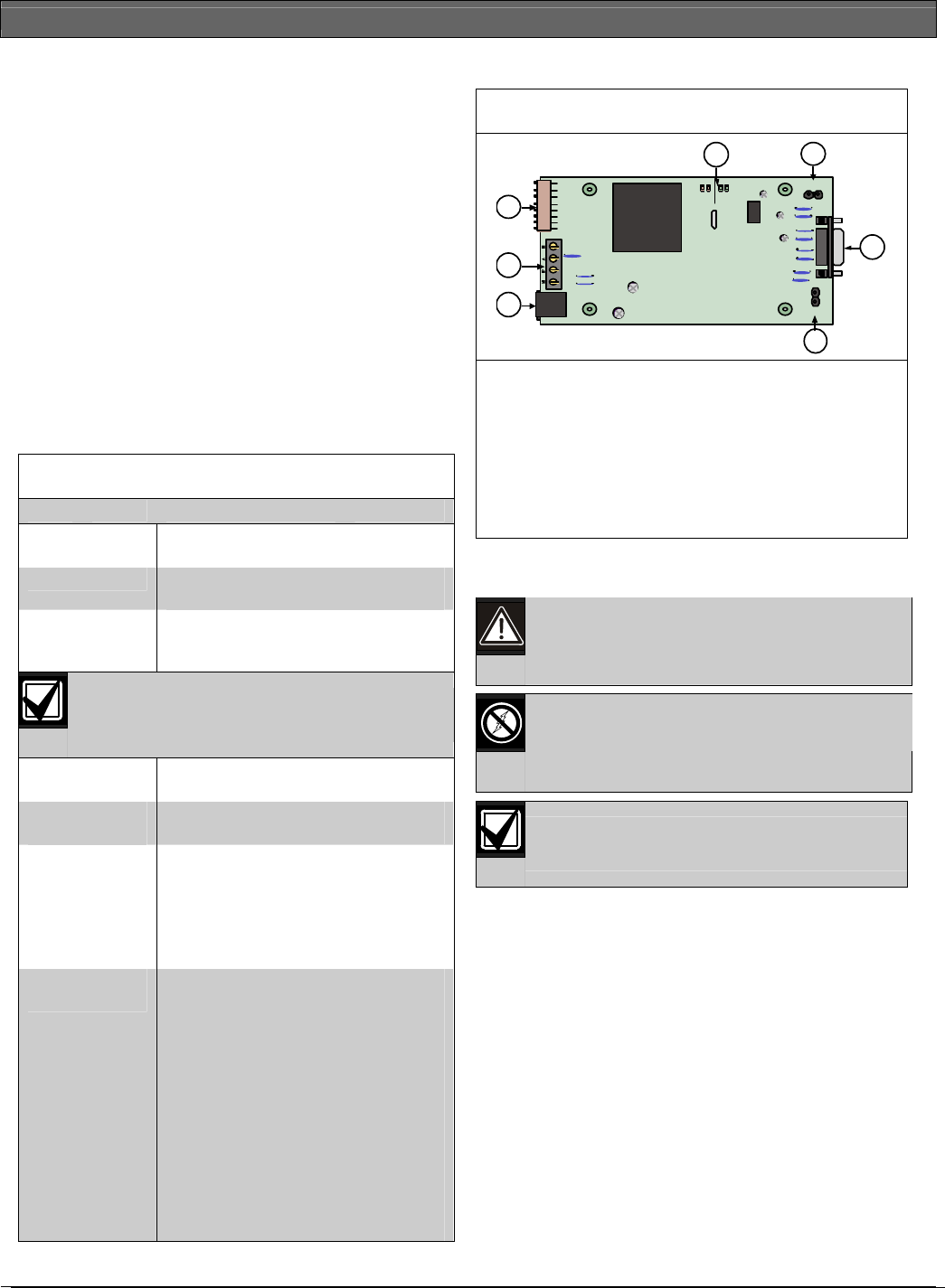
Figure 1: DX4010i Component Layout
SER
RxTx
BUS
RxTx
LED
ENABLE
DB9 GND
ENA BLE
P1
P6
P2
P3
1
2
3
4
5 6
7
1- DB9 GND enable pins (P1)
2- RJ-16 data bus connector (P3)
3- Data bus (TS1)
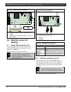
4- Address DIP switches (S1)
5- Diagnostic LEDs
6- Diagnostic LED enable pins (P2)
7- DB9 DTE RS-232 connector (P6)
3.0 Installation Standards
Failure to follow the instructions in this
manual can result in personal injury or
damage to the equipment.
The DX4010i contains static-sensitive
components and must be handled with
care. Follow anti-static procedures when
handling the modules.
Test according to NFPA 72 if used in fire
applications.
1. Disconnect power to the control panel by
unplugging the transformer and removing the red
battery lead.
2. Remove screws from enclosure cover to access the
DX4010i board.
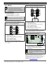
3. Connect circuit wiring and install jumper pins.
Refer to Section 4.0 Wiring on page 5.
4. Replace enclosure cover.
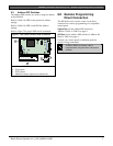
5. Connect a serial cable to the serial device. Refer to
Section 7.0 DB9 DTE RS-232 Connector (P6) on
page 10.
6. Reapply power to the control panel.