


DX4010i | Installation Instructions | 7.0 DB9 DTE RS-232 Connector (P6)
10 Bosch Security Systems, Inc. | 1/05 | 4998141106C
7.0 DB9 DTE RS-232
Connector (P6)
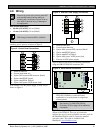
The DX4010i serial port is wired as a DTE device.
•
If the connected device is a data carrier
equipment (DCE) device (most common, such
as an external modem), a straight through 9-pin
to 9-pin, or (DTE to DCE) 9-pin to 25-pin cable
may be used.
•
If the connected device is a DTE device (such as
a PC serial port), a null-modem (DTE to DTE)
9-pin to 9-pin, or null-modem 9-pin to 25-pin
cable is required.
Consult the operating manual provided with your
compatible device for wiring requirements.
If you are using an alternate configuration, you must
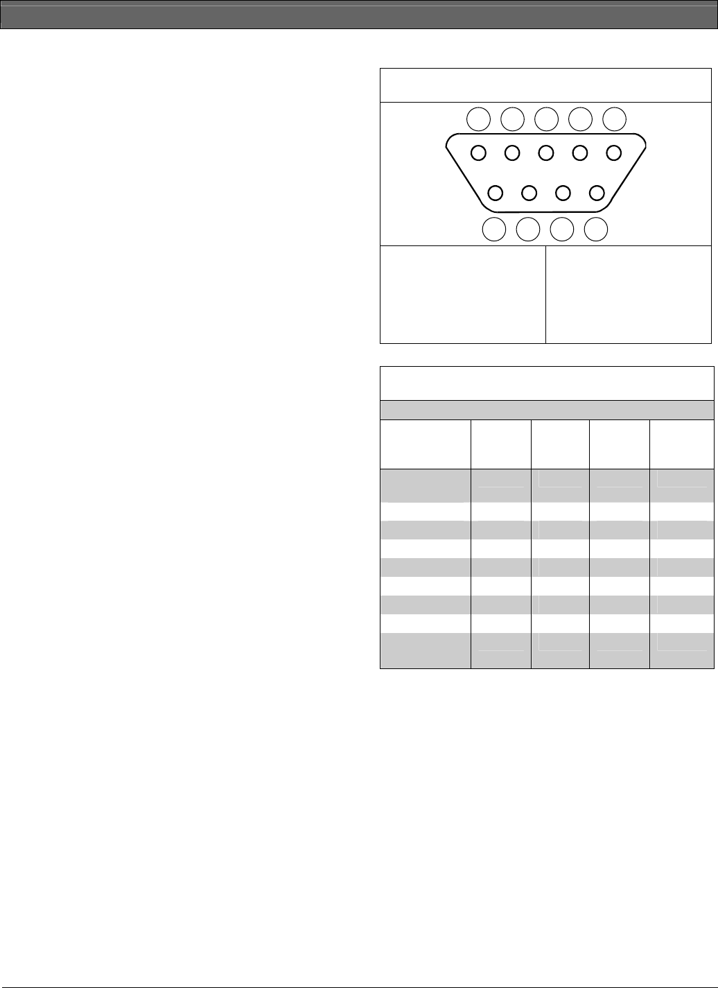
make a custom cable (refer to Figure 8 and Table 5).
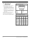
Figure 8: DB9 Connector Layout
1 2 3 4 5
6 7 8 9
1- DCD
2- RxD
3- TxD
4- DTR
5- GND
6- DSR
7- RTS
8- CTS
9- RI
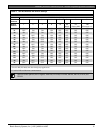
Table 5: Alternate Wiring Configuration
DX4010i
9-Pin DTE
Connector
DCE
(9-pin)
DTE
(9-pin)
DCE
(25-pin)
DTE
(25-pin)
1: DCD
(not used)
1: DCD 1: DCD 8: DCD 8: DCD
2: RxD
2: RxD 3: TxD 3: RxD 2: TxD
3: TxD
3: TxD 2: RxD 2: TxD 3: RxD
4: DTR
4: DTR 6: DSR 20: DTR 6: DSR
5: GND
5: GND 5: GND 7: GND 7: GND
6: DSR
6: DSR 4: DTR 6: DSR 20: DTR
7: RTS
7: RTS 8: CTS 4: RTS 5: CTS
8: CTS
8: CTS 7: RTS 5: CTS 4: RTS
9: RI
(not used)
9: RI 9: RI 22: RI 22: RI