


AMC2 4W Installing | en 45
Bosch Security Systems Installation manual F.01U.024.965 | V.4 | 2006.09
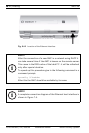
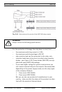
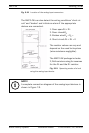
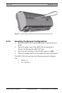
Fig. 5.22 Location of the analog input connectors
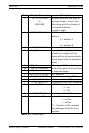
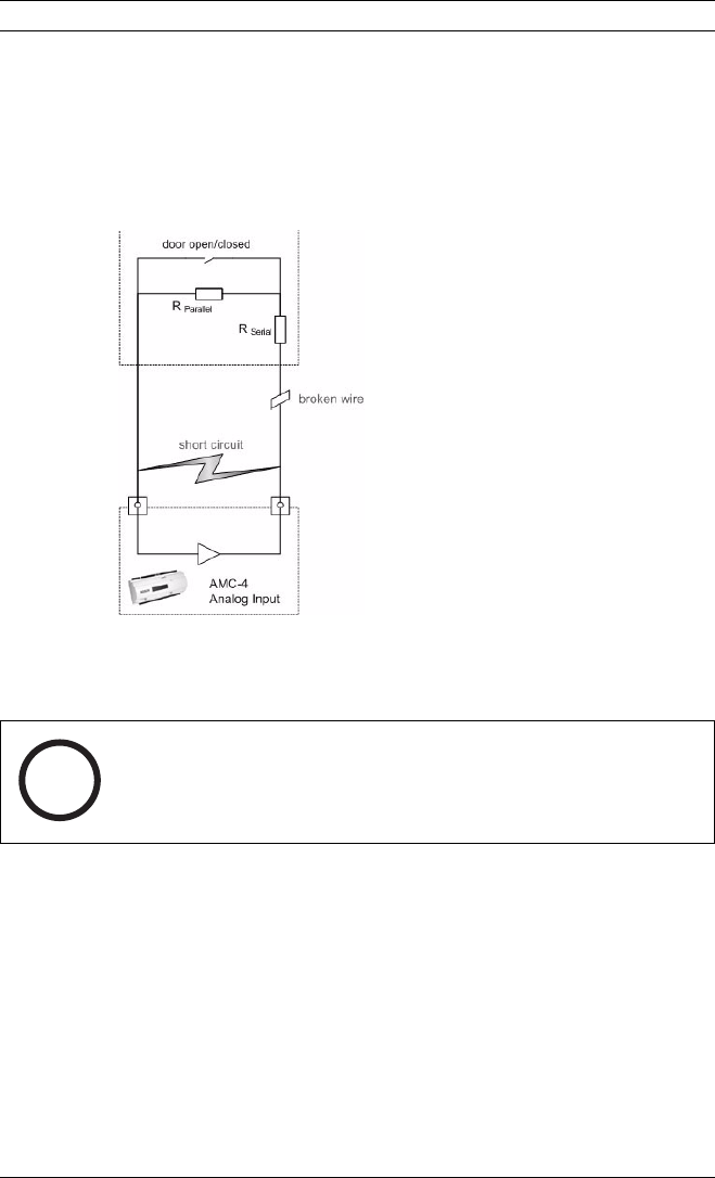
The AMC2 4W can also detect the wiring conditions ‘short cir-
cuit’ and ‘broken’ and initiate an alarm if the appropriate
devices are connected.
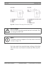
1. Door open:R
S
+ R
P
2. Door closed:R
S
3. Broken wire:R
S
+ R
P
=
4. Short circuit:R
S
+ R
P
= 0
The resistor values can vary and
depend on the used lock system
(wire resistance negligible).
The AMC2 4W package includes
2,2 kΩ resistors using for reserves
for the R
S
and the R
P
resistor.
Fig. 5.23 Operating modes of a lock
using the analog input device
i
NOTE!
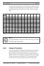
A complete connection diagram of the analog input devices is
shown in Figure 7.8.