AMC2 4W Introduction | en 15
Bosch Security Systems Installation manual F.01U.024.965 | V.4 | 2006.09
3.2 Equipment Configuration
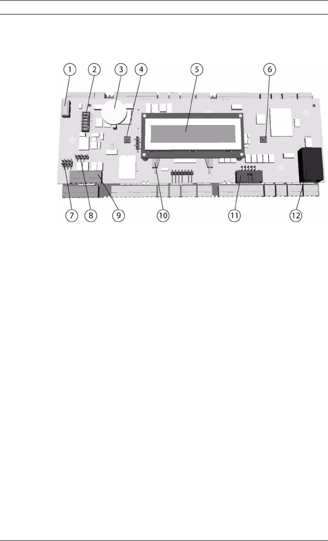
Fig. 3.3 Upper circuit board with display (top side)
1. Internal tamper contact
2. DIL switch for RS-485 address selection, protocol and RS-
232/RS-485 selection
3. Lithium battery for buffering of static RAM and real time
clock (RTC). The battery shall be replaced by qualified per-
sonnel every ten years or if indicated by an appropriate
event.
4. Reset push button - available by using the srew driver
5. LC Display
6. Push button to select the display view - available by using
the push button on the top of the housing
7. Jumper: Potential equalization between different mass sys-
tems and protective earth (shield)
8. Jumper: interface selector RS-485 Host connection, RS-
485 two wire or RS-485 four wire (depends on external
wiring)
9. Configurable RS-485 host interface (pluggable screw con-
nector)
10. Docking station for the compact flash


