


4
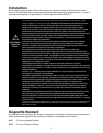
WARNING!
!
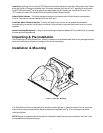
All devices should be mounted in accordance with the manufacturer’s instructions and
securely fastened to vehicle elements of sufficient strength to withstand the forces applied
to the device. Ease of operation and convenience to the operator should be the prime
consideration when mounting the siren and controls. Adjust the mounting angle to allow
maximum operator visibility. Do not mount the Control Head Module in a location that will
obstruct the drivers view. Mount the microphone clip in a convenient location to allow the
operator easy access. Devices should be mounted only in locations that conform to their
SAE identification code as described in SAE Standard J1849. For example, electronics
designed for interior mounting should not be placed underhood, etc.
Controls should be placed within convenient reach* of the driver or if intended for two
person operation the driver and/or passenger. In some vehicles, multiple control switches
and/or using methods such as “horn ring transfer” which utilizes the vehicle horn switch to
toggle between siren tones may be necessary for convenient operation from two positions.
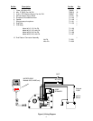
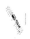
Amplifier Connections
Siren Amplifier Connector - Refer to the Wiring Diagram in Figure 5 (page 10) for detailed
information about the amplifier connections. As a standard feature, the 4000 Series of Siren are
equipped with a combination plug-in terminal block/connector. To terminate the wires, strip
approximately 1/4" of insulation from the end of each wire and insert it in the appropriate hole in the
terminal block. Tighten the setscrew and proceed to the next connection.
Should you ever have to remove the unit, loosen the security screws and pull the terminal block
straight out. It will unplug from the siren, leaving the wiring in place.
Terminal Block Connections
-V - Connect to the negative terminal of the battery. This supplies ground (earth) to the siren. Use #14
gauge wire.
+V - Connect to a positive +12 volt DC source (+24 volts for Models 4024 and 4025). It is
recommended that the user protect this wire with a 10 Amp fuse or circuit breaker located at the
power source (5 Amp fuse for Models 4024 and 4025). Use #14 gauge wire.
NUIT - Connect to a switch which will supply ground (earth) when ON. Use #14-16 gauge wire.
ACTIVEZ - Connect to a switch will supply ground (earth) when ON. Use #14-16 gauge wire.
HP1 - Speaker - Connect to the wire from 100W ( 11 ohm ) speaker terminal 1.
HP2 - Connect to the wire from one 100W ( 11 ohm ) speaker terminal 2.
SETUP AND ADJUSTMENT
P.A. Volume Adjustment - Public Address volume is set by the sliding volume control located on
the front of the microphone. Set this control to give the desired PA Volume level. The user may
adjust this control at any time during use.
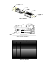
Tone Selection - Referring to Figure 2 and Figure 3 and the Siren Tone Chart, Figure 4, set the 16
position rotary switch SW1 (located inside the siren) to the number which corresponds to the desired
tone. Unless otherwise specified at the time of order, the default setting is 0 (Police).