


2.5 ELECTRICAL SUPPLY
Mains supply: 230V ~, 50 Hz, 180 watts.
External fuse: 3A., Internal fuses: 2AT HRC(F1), and 1 AF (F2).
2.6 GAS SUPPLY
The boiler requires 2.76 m
3
/h (97.5 ft
3
/hr) of natural gas with a
calorific value of 37.78 MJ/m
3
(1014 Btu/ft
3
) or 1.07 m
3
/h (37.8
ft
3
/hr) of propane with a calorific value of 95.65 MJ/m
3
(2568
Btu/ft
3
). The meter governor should deliver a dynamic pressure
of 20 mbar (8in w.g.) at the appliance, equivalent to a pressure of
about 19-19.5 mbar at the gas valve on natural gas or 37.0 mbar
(14.8in w.g.) at the appliance for propane.
The gas meter and supply pipes must be capable of supplying
this quantity of gas in addition to the demand from any other
appliances being served. The table below gives an indication of
limiting gas pipe lengths and the allowance to be made for
fittings. Refer to BS6891 for further information.
The complete installation, including the gas meter, must be
tested for soundness and purged. Refer to BS 6891.
Note: Each fitting used in the gas line from the meter is
equivalent to a length of straight pipe which must be added to
the straight pipe length to give the total length.
i.e.: Bend = 0.5 metres, Tee = 0.5 metres, 90° Bend = 0.3
metres.
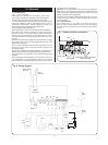
2.7 PACKING
The appliance and flue components are packaged separately.
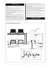
2.8 GENERAL INSTALLATION
The appliance is for connection to a sealed system only.
The specified ventilation openings made into a wall or
compartment door must not be obstructed.
If the appliance is to be fitted into a compartment then the
compartment must conform to the requirements of BS 6798:
1987: Section 7.
Do not place anything on top of the appliance.
The clearances specified for servicing must be maintained.
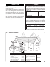
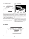
2.9 FLUE
The appliance has a multi-directional fanned flue system.
The standard telescopic flue assembly length is from 127mm to
350mm.
Extension flue lengths available are from 350mm to 2500mm.
An optional vertical flue kit to provide for flue lengths up to
3000mm including vertical flue terminal.
A terminal guard, Type K2, GC 393 553, is available from Tower
Flue Components, Vale Rise, Tonbridge, TN9 1TB.
Do not allow the flue terminal fitted to the outside wall to
become obstructed or damaged.
A kit for internal fixing of the flue is available separately.
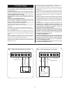
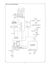
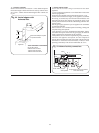
2.10 CONTROLS
The electronic control system and gas valve modulate the heat
input in response to the domestic hot water temperature and
central heating setting between minimum and maximum.
The Central Heating Temperature control knob provides for the
selection of domestic hot water only (Turned fully anti-clockwise)
or central heating and domestic hot water (Turned clockwise).
A facia mounted programmer is available as an optional extra. A
remote mounted programmer may be connected to the
appliance.
There is provision for the connection of a mains voltage room
thermostat and/or a frost thermostat.
The electronic controls prevent rapid cycling of the appliance in
the central heating mode.
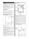
2.11 SYSTEM NOTES
IMPORTANT
Check that no dirt is left in either the gas or water pipework as
this could cause damage to the appliance. The heating system
should be flushed and treated in accordance with the
recommendations of BS 7593:1992. Thoroughly flush cold water
mains supply and purge the gas supply before finally connecting
the appliance.
The water pipe connections throughout a sealed system must be
capable of sustaining a pressure of up to 3 bar.
Radiator valves must conform to the requirements of BS
2767:1991.
The relief valve discharge must be directed away from any
electrical components or where it would cause a hazard to the
user.
A drain cock to BS 2879 must be fitted to the lowest point of the
system.
For circuit design purposes it is important that due note is taken
of the information given in Table 3, section 3 relating to the
available pump head.
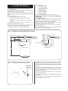
2.12 SHOWERS, BIDETS, TAPS AND MIXING VALVES
Hot and cold taps and mixing valves used in the system must be
suitable for operating at mains pressure.
Thermostatically controlled shower valves will guard against the
flow of water at too high a temperature.
Hot and cold mains fed water can be supplied direct to an over-
rim flushing bidet subject to local Water Company requirements.
With all mains fed systems the flow of water from the individual
taps will vary with the number of outlets operated
simultaneously and the cold water mains supply pressure to the
property. Flow balancing using “Ball-o-Fix” type valves is
recommended to avoid an excessive reduction in flow to
individual outlets.
2.13 SAFETY CONSIDERATIONS
The appliance must not be operated in a waterless condition.
The appliance must not be operated with the boiler inner casing
cover removed.
Work must not be carried out on the appliance without the gas
and electricity supplies being switched off.
Checks must be made to ensure that the ventilation openings
made into walls and partitions are unobstructed and the correct
size.
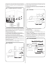
2.14 OPERATION
Domestic Hot Water:
With a demand for hot water the burner
will light at its maximum setting and then automatically adjust
its output to maintain the temperature of the delivered water.
When hot water is no longer required, the burner will extinguish.
The fan and pump may continue to run for a short period to
dissipate the residual heat from the appliance.
Central Heating: With a demand for heating the burner will light
at its minimum setting and gradually increase to give a
controlled temperature rise. When the required heating
temperature is achieved the output of the appliance is then
automatically adjusted to maintain the temperature of the
system. The output can reduce down to a minimum of 7.5 kW. If
the system no longer requires even the minimum output to
maintain the desired room temperature the burner will
extinguish. The fan and pump may continue to run to dissipate
the residual heat from the appliance. The appliance will remain
off for a fixed period before re-lighting to automatically meet the
system requirements.
Domestic Hot Water and Central Heating: The appliance will
supply heat to the central heating system as required. A demand
for domestic hot water at a tap or shower will override the
central heating requirement for the period of the domestic hot
water demand. When hot water is no longer required the
appliance will return to the central heating state and its normal
mode of operation. The fan may continue to run to dissipate the
residual heat from the appliance as necessary.
2.15 DOMESTIC SUPPLY
Devices capable of preventing the flow of expansion water must
not be fitted unless separate arrangements have been made.
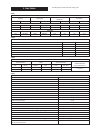
3
Total length of gas supply pipe Pipe size
(metres) (Ømm)
36912
Propane
Gas Discharge
1.5 – – – 15
Rate
8.0 5.2 4.2 3.6 22
(m
3
/hr)
15.9 8.8 8.5 7.2 28
Natural Gas
8.7 5.8 4.6 – 22
18.0 12.0 9.4 – 28
Gas
Discharge
Rate
(m
3
/hr)