


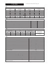
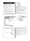
Connect the gas, water and pressure relief valve connections to
the appliance. The primary system should be flushed and
treated in accordance with the recommendations of
BS7593:1992.
If the air and flue duct assembly is to be fitted from inside the
room then the ducts must be adjusted to length, assembled and
inserted through the wall at this stage before fitting the flue
turret to the appliance. Refer to Section 11.3 following for the
assembly of the air and flue ducts.
Remove the fan. See Section 14.3(e).
11.3 AIR AND FLUE DUCT PREPARATION AND ASSEMBLY
Check the contents of the standard flue kit against the packing
list. Similarly check the extension kits if applicable.
Remove all the packing from the flue and terminal assembly.
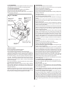
The standard flue kit accommodates a flue assembly up to
350mm long measured from the appliance casing to the outer
wall face. See dimension
L, Figs.13 and 14.
When dimension
L is greater than 350mm extension flue
assemblies will be required.
It will not be necessary to cut either the ducts attached to the
turret or the terminal unless
L = 350 to 450mm.
Measure and cut the extension ducts to length ensuring that the
cuts are square and free from burrs. Always check the
dimensions before cutting the ducts.
All extension duct dimensions refer to the straight lengths. The
socketed ends must not be removed or included in any
measurement.
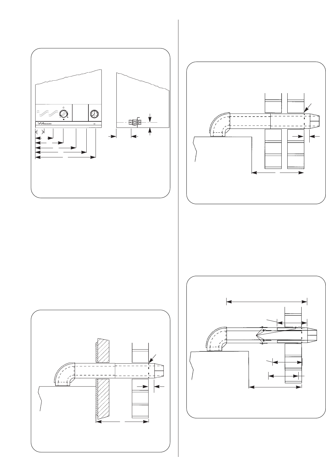
11.4 EXTERNAL FITTING OF THE DUCT ASSEMBLY
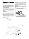
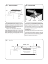
Measure distance L.
Side flue duct length =
L + 184mm. See Fig. 14.
Rear flue duct length =
L + 181mm. See Fig. 13.
Do not cut either the turret or the terminal assembly ducts
unless
L = 350 to 450mm.
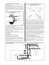
1. Should L = 350 to 450mm then cut the terminal assembly
ducts reducing the length of the ducts to 200mm. Then cut each
extension duct to 200mm (See Fig. 15). Assemble the flue as
described below ensuring the correct length (
L+184mm for side
flues or
L+181mm for rear flues).
12
Fig. 13. Rear flue.
Fig. 14. Side flue.
Fig. 15. 350-450 Special.
Rear face of appliance
and face of mounting
wall
External
wall face
40mm
Make
good
L
Appliance casing
Fixing screws
Flue extension
duct length
200mm
Air
extension
duct
length
200mm
Terminal assembly
reduced to 200mm
Turret assembly
with full
standard
duct
lengths
Rear flue
L + 181mm
Side flue L + 184mm
L = 350mm-450mm
Appliance side panel
External
wall face
40mm
Make
good
L
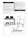
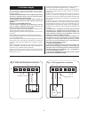
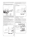
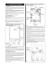
Fig. 12. Appliance pipework connections.
(A)
100mm
36.5mm
(B)
(C)
(D)
(E)
(F)
A Safety Relief = 50mm
B CH Flow = 95mm
C DHW Out = 160mm
D Gas Inlet = 225mm
E Mains Cold Water In = 290mm
F CH Return = 355mm