


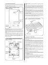

11.5 INTERNAL FITTING OF THE DUCT ASSEMBLY
The rubber sealing gasket and the clamping ring are available from
Worcester Heat Systems.
Measure and cut the ducts as previously described for external
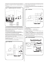
fitting (Section 11.4). Fix the ducts to the terminal and fit the rubber
sealing gasket and clamp to the terminal. Centralise the gasket and
tighten the clamping ring. See Fig. 19. Slide the flue centering ring
onto the air duct and tighten the screw. See Fig. 20. Fix the ducts
and terminal assembly to the flue turret as described in Section 11.4
preceding.
Apply the plastic tape provided to the last section of flue where it
will be sealed to the external brickwork.
Push the assembly through the wall so that the gasket flange is
against the outside face of the wall. See Fig. 20.
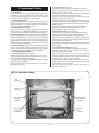
Align the flue turret with the socket on the appliance, push the
turret down to fully engage it and clamp in place with the turret
clamping ring. See Fig. 18.
Refit the fan and replace the inner casing cover.
Seal the gap around the duct with the flexible seal provided and
make good. See Fig. 20.
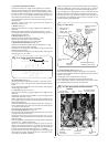
11.6 FLUE BENDS
See Figs 21 and 22.
Measure distances
X, Y and Z as appropriate.
Side flue duct length =
X + 63mm. See Fig. 21.
Rear flue duct length =
X + 60mm. See Fig. 21.
Cut the flue and air ducts which are to make up the first section
X such that both the assemblies are of equal length (either X +
63mm or
X + 60mm). Extensions will be necessary to allow X to
be larger than 250mm.
Any extension ducts are fixed by drilling a pilot hole through the
hole in the duct or elbow and screwing the self tapping screw
provided into the two ducts. (See Fig. 21).
The length
Y is the distance between bends the ducts must be
cut to
Y – 162mm. The swaged ends must be removed from the
extension tube and only the air duct needs fixing. See Fig. 21.
Z is the final flue length from the last elbow to the outside face of
the external wall. The first duct sections fitted to the elbow must
have unswaged ends. The length of the air ducts should be
Z –
196mm. The inner flue duct must be 30mm longer than the air
duct. If
Z – 196mm is less than 160mm then the terminal section
will need to be shortened to the same length as the extension flue
section fitted to the elbow (length
Z – 100). If flue extensions are
needed to attain the required length care must be taken to ensure
that the last section of flue is longer than 260mm.
Each extension must be connected to the previous section of flue
or bend by firstly fitting the inner flue ducts together and pilot
drilling and fixing as above (See Fig. 21). Then the outer air ducts
can be similarly fixed using the pair of screws provided. The flue
terminal section can then be telescopically adjusted and fixed as
before (See Fig. 21), ensuring the correct length of
Z – 41.
The silicon sealant supplied should be applied to the flue ducts
which engage into elbows. See Fig. 21.
From inside, push the assembly through the wall
Align the flue turret with the socket on the appliance, push the
turret down to fully engage it and clamp in place with the turret
clamping ring. See Fig. 18.
Make good the internal and external brickwork or rendering.
Refit the fan. Do not use any sealant on the joint. Replace the
inner casing cover.
14
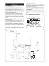
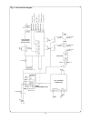
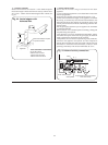
Fig. 21. Flue bends.
56mm
Z Ð 41mm
56mm
Side flue
X + 63mm
Rear flue X + 60mm
Z
Y
X
Y
Ð 162mm
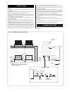
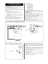
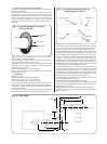
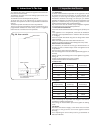
Fig. 19. Terminal assembly for internal
fitting of the flue.
Flue centring ring Flue terminal
Flue duct
Rubber
sealing
gasket
Air duct
Rubber sealing
gasket
Clamping ring
Flue terminal
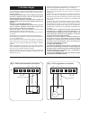
Fig. 20. Duct and terminal assembly for
internal fitting of the flue.