


Adequate, non-contaminated combustion air must be supplied to the water heater.
In a confined space with a volume of less than 50 cubic feet per 1000 BTUH, the space must be
vented at the floor for combustion air, and at the ceiling for ventilation. The air can be supplied from
either inside or outside of the building as conditions allow.
Care must be taken to insure an adequate air supply for the water heater.
A. Install equipment only where the water heater will have satisfactory combustion, proper venting
and the maintenance of temperature at safe limits all around the unit under normal operating condi-
tions. Free circulation of air around the water heater is essential. If the air supply is inadequate,
introduce outside air. Any temperature above 90°F around the heater indicates a need for additional
air (see NFPA 31 for air requirements).
B. In addition to air needed for combustion, air may be required for draft control; cooling off; control-
ling dew point; heating; drying; oxidation or dilution; safety exhaust; odor control; and compressors.
C. Make sure air around the water heater is adequate for personal comfort and working conditions.
D. Check for proper draft. Place a draft gauge in the chimney above the draft diverter. Drafts should
be at least -0.02” W.C. and less than -0.05” W.C. while the water heater is in operation.
Unconfined space: No additional combustion and ventilation air is required if the volume of the
space is greater than 50 cubic feet per 1,000 BTUH of the combined total input of all equipment
installed in that space. Rooms leading directly to the space through openings which cannot be
closed are considered part of the unconfined space.
Confined space: When the unit will be installed in a space with a volume of less than 50 cubic feet
per 1,000 BTUH, the space must be vented at the floor for combustion air and at the ceiling for venti-
lation. This air can be supplied from either inside or outside of the building as conditions allow (refer
to NFPA 31 or local codes).
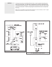
A. Inside air supply: Provide two permanent openings; one within 12” of the top of the enclosure and
one within 12” of the bottom, leading directly to room(s) of sufficient volume so that the combined
volume of all the space meets the criteria for unconfined space. Each opening required a minimum
free area of one (1) square inch (two square inches total) per 1,000 BTUH of the combined total
input of all equipment installed in the enclosure, but not less than 100 square inches.
B. Outside air supply: Provide two permanent openings; one within 12” of the top of the enclosure
and one within 12” of the bottom. These openings must lead directly to crawl and attic spaces lead-
ing directly to the outside of the building.
1. Leading directly to outside or through vertical ducts: Each opening (top and bottom) requires a
minimum free area of one (1) square inch (two square inches total) per 4,000 BTUH of the combined
total input of all equipment installed in the enclosure.
2. Leading to the outside through horizontal ducts: Each opening (top and bottom) requires a mini-
mum free area of one (1) square inch (two square inches total) per 2,000 BTUH of the combined
total input of all equipment in the enclosure.
Louvers and grilles: In calculating the “free” area in Equipment Located in Confined Spaces,
consider the blocking effects of louvers, grilles, or screens protecting openings. The screens cannot
be smaller than one (1) inch of mesh. If the “free” area of a louver or grille is known, it should be
used in calculating the size opening required to provide the “free” area specified. If the design and
“free” area is not known, assume wood louvers have 20% to 25% “free” area, and metal louvers and
grilles 60& to 70%. Fix louvers and grilles in the open position or interlock with the equipment so
they are opening automatically during equipment operation.
COMBUSTION AIR
VENTILATION AIR
NOTE: All ducts
must have the
same cross sec-
tional area as the
free area of each
opening to which
they connect. The
minimum side
dimension of a rec-
tangular duct must
be no smaller than
three (3) inches.
Caution: Operation
of exhaust fans,
ventiliating sys-
tems, power burn-
ers, induced draft
systems, or fire-
places may create
conditions that
require special
attention to avoid
unsatisfactory
operation of
installed equip-
ment.