


Please read this Guide thoroughly before
assembling your cleaner. Pay particular attention
to the product diagram, assembly instructions,
and part names.
Begin by locating and organizing all parts
before assembly.
Familiarize yourself with the parts and where they go.
Following this User’s Guide will let you get the best performance
from your BISSELL Little Green for many years.
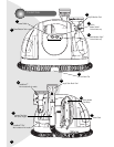
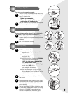
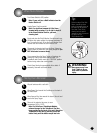
Clean/Solution Tank. The Clean/Solution Tank is the
tank to your left as you face the unit looking at the black
power switch.
PowerSwitch (Black). Turns on the unit.
Dirty/Collection Tank. The Dirty/Collection Tank is the
tank to your right as you face the unit looking at the
black power switch.
Built-In Heater Switch (Red)*. The Little Green ProHeat
®
models give you the ability to raise the water temperature for
improved cleaning performance based on your cleaning needs.
Heat Indicator Light*. After turning the Built-In Heater
Switch on, the Heat Indicator Light will illuminate,
indicating the heater has reached the correct temperature.
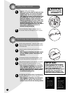
Flex Hose Clip. The clip guides the storage of the
vacuum flex hose around the unit.
TurboBrush Clip*. Attaches to the unit for storage of the
TurboBrush.
Vacuum Flex Hose with Spray Trigger. The hose is
stored around the base and on the back of the Little
Green. Cleaning tools attach to the Spray Trigger.
TurboBrush*. The TurboBrush has a rotating brush.
Tough Stain Brush Tool. The standard tool that attach-
es to the vacuum Flex Hose.
How To Use This Guide
1.
2.
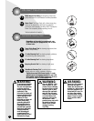
WARNING:
Do Not plug in your Little Green
until you have completely
assembled it according to the
following instructions and
have become familiar with
all instructions and operating
procedures.
Little Green
®
Product Features
1.
2.
3.
4.
5.
6.
7.
8.
9.
10.
5