


Part No 790294 Form No F062906A
12
QL2300 Owner’s Manual
MAINTENANCE
P
ERIODIC MAINTENANCE
Periodic maintenance should be performed at the following intervals:
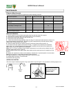
Maintenance Operation Every use Every 5 hours (daily) Every 10 Hours Every 25 Hours
Inspect for loose, worn or damaged parts.
z
Check engine oil and air filter
z
Clean hose
z
Engine (See Engine Manual)
Inspect battery for damage or leak
z
Keep engine free of debris
z
Check battery terminal for corrosion
z
Check for excessive vibration
z
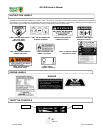
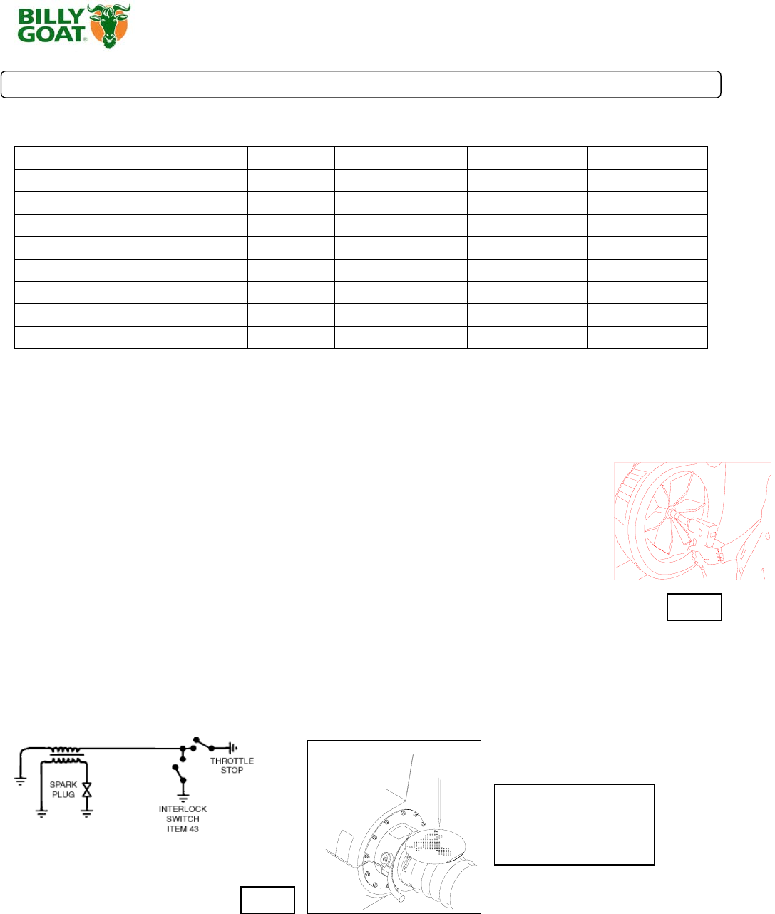
INTERLOCK SYSTEM
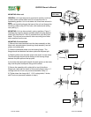
With hose coupler installed (as shown in Fig. 8) the switch is open & engine is not grounded out, allowing engine to run.
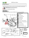
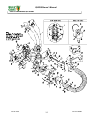
IMPELLER REMOVAL
1. Wait for engine to cool and disconnect spark plugs from the both sides of the engine.
2. Disconnect the negative battery cable (black) (item 12) from the battery.
3
. Remove the hose coupler assy from the unit (item 36).
4. Remove the hose boom assembly.
5. Remove the intake housing assembly (item 33) using 1/2" socket and socket wrench to remove (12)
locknuts and washers (item 60 & 63). Be careful to place intake assembly to the side without putting
excess strain on safety switch wire harness
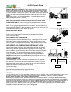
6. Remove impeller bolt and lock washer using 5/8" socket and impact wrench (see fig. 6).
7. Once bolt is removed impeller should slide out freely. If impeller will not slide free on crankshaft,
obtain a 3/4"-10 x 3" bolt and thread it into the nut that is welded onto the center of the impeller and
tighten slowly to push the impeller off the crankshaft.
Note:
3/4"-10 x 3" bolt is included in each impeller replacement kit or the bolt can be ordered from your
local Billy Goat Dealer (part no. 790214).
8. When impeller is free of the engine shaft, align impeller with the opening and pull it straight out of the
housing.
9. Using a new impeller bolt, washer, and lockwasher, reinstall new or repaired impeller in reverse order.
Note: Be sure spacer is in place behind impeller before tightening.
10. Tighten impeller bolt. Torque impeller bolt to [60 Ft. Lbs. (81.4 N.m)].
11. Repeat steps 2 through 5 in reverse order.
12. Reinstall spark plug wires.
Fig. 8
Fig. 6
Hose must be installed
and switch lever must
engage switch for
engine to start.