


Form No F060711D 17 Part No 840245
MV650SPH Self-Propelled Vacuum Owner’s Manual
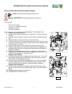
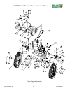
INSTALLING NEW DRIVE CHAIN/ALIGNMENT/TENSION
READ all safety instructions before servicing unit.
DISCONNECT spark plug wire before servicing unit.
Tools required:
- 7/16” and 1/2” socket.
- 7/16” and 1/2” combination wrench.
- “Needle nose” pliers
- Flat head screwdriver
Allow the engine to cool completely and DISCONNECT THE SPARK PLUG.
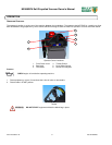
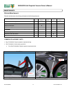
1. Unfasten and remove the guard.
2. Rotate left rear wheel to bring the chain “master link” into view on the axle
sprocket.
3. Using the needle nose pliers carefully remove master link retaining spring
clip.
4. Slide the master link from the chain and remove the chain.
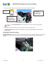
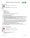
5. Thread the new chain onto the sprockets, place the ends of the chain on the
axle sprocket, this makes it easier to hold the chain in place when you slide
the new master link in place.
6. Install the new master link and CAREFULLY install the retaining clip.
7. Rotate left rear wheel to find the location where the chain is tightest (there
are always slight variations in the sprockets that make the chain tighter at
places in its rotation).
8. Rotate the axle several times and listen for “popping” or “clacking” this
indicates too much tension on the chain or misalignment of the chain. Skip
to Step 12 if no “popping” or “crackling” occurs.
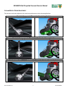
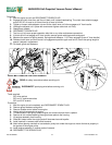
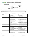
Improper Chain Tension
9. At the point where the chain is tightest check the chain to for ¼” to ½” total
slack halfway between the axle sprocket and the transmission sprocket.
Skip to Step 11 if the deflection is correct.
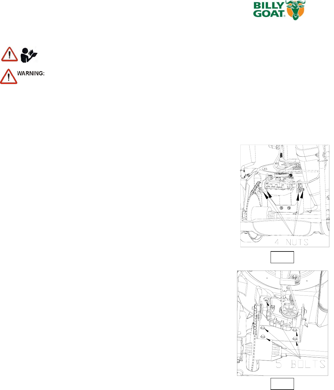
10. Loosen 4 nuts holding the bearing bracket (see Fig 1) slide it very slightly
forward to tighten the chain or slide backward to loosen. Tighten 4 nuts
back then check the chain deflection. Repeat this step if necessary.
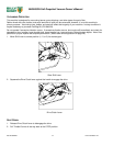
Improper Chain Alignment
11. Loosen 5 bolts securing the drive system (see Fig 2) slide it left or right
then check the alignment using straight edge. Tighten 5 bolts then repeat
Step 8.
12. Reinstall the guard and all of its fasteners.
13. RECONNECT THE SPARK PLUG.
Fig 2
Fig 1