Part No. 800012 Form No. F021402A
Page 9 of 12
OPERATION continued
1616
1616
16
PROPULSION self propelled only
16.616.6
16.616.6
16.6
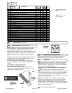
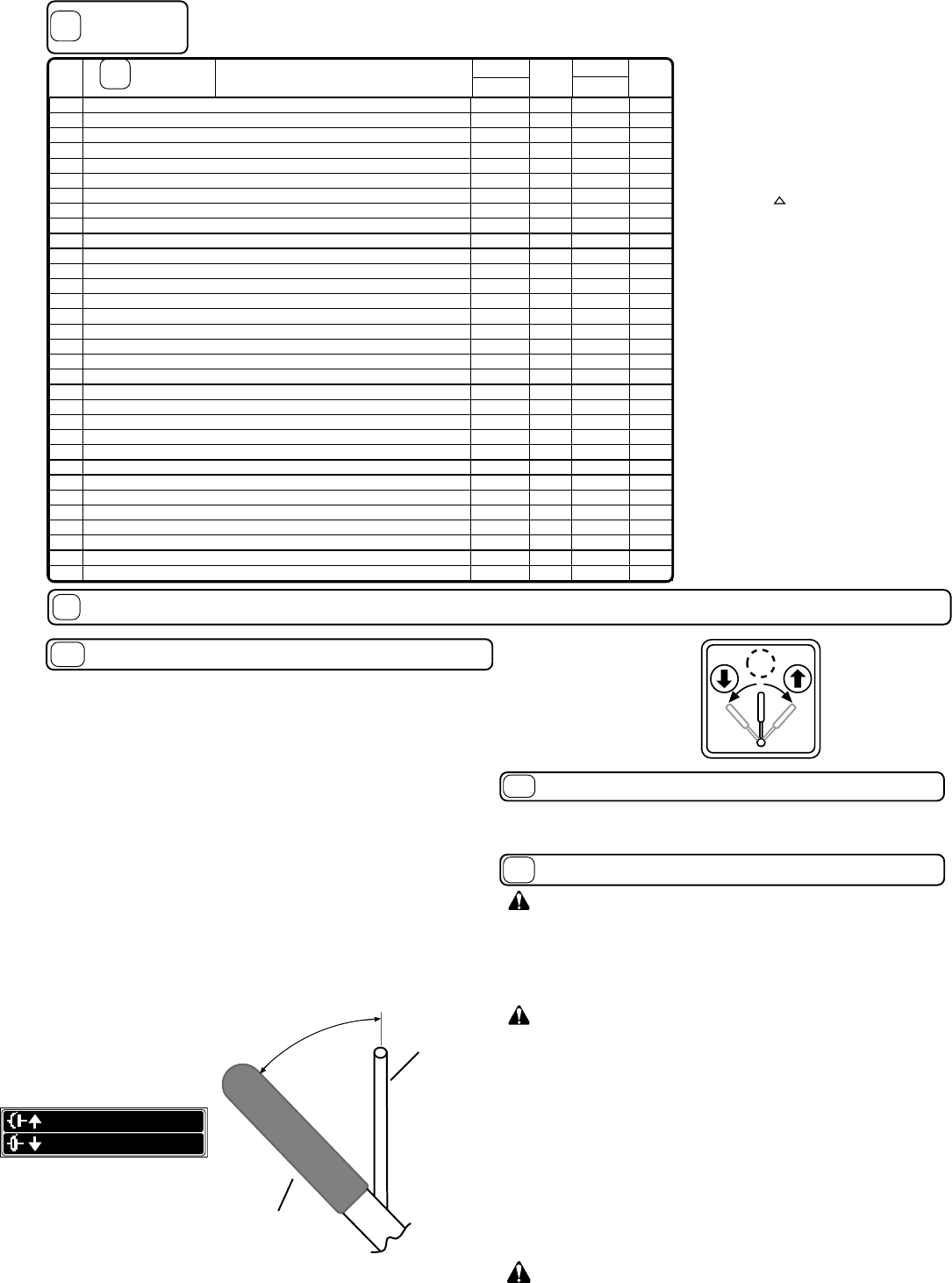
PROPULSION: BG self-propelled vacuums are equipped
with 1 forward gear, neutral and reverse. With the engine
running, the bail in released position and brake in on
position, select desired drive gear. Lift bail against handle to
engage drive (see figure 1 & 2). Smoothly engage the bail.
Use good judgement when operating the self-propelled
drive.
Using neutral, on level terrain is advisable when maneuver-
ing in tight areas. This increases operator control, and can
prevent bumping into nearby objects.
Do not force-shift gears of transmission. To assist gear
meshing, it may be necessary to partially engage bail while
shifting.
To stop machine, release operator's bail.
For reverse - Set Throttle to Idle.
With operator's bail released, pull shift lever reverse
position. Then smoothly lift operator's bail against handle.
Release bail to stop (see figure 2).
Never store engine indoors or in enclosed poorly venti-
lated areas with fuel in tank, where fuel fumes may reach an
open flame, spark or pilot light, as on a furnace, water heater,
clothes dryer or other gas appliance.
If engine is to be unused for 30 days or more, prepare as
follows:
Be sure engine is cool. Do not smoke. Remove all
gasoline from carburetor and fuel tank to prevent gum deposits
from forming on these parts and causing possible malfunction
of engine. Drain fuel outdoors, into an approved container,
away from open flame. Run engine until fuel tank is empty and
engine runs out of gasoline.
Do not store with debris in bag.
NOTE: Fuel stabilizer (such as Sta-Bil) is an acceptable
alternative in minimizing the formation of fuel gum deposits
during storage. Add stabilizer to gasoline in fuel tank or
storage container. Always follow mix ratio found on stabilizer
container. Run engine at least 10 min. after adding stabilizer to
allow it to reach the carburetor.
Using two people to lift machine is recommended. Lift holding the
handle and front of nozzle. Secure in place during transport.
HANDLING & TRANSPORTING:
16.416.4
16.416.4
16.4
STORAGE
16.516.5
16.516.5
16.5
Bail Down
Disengages
Drive
Handle
Bail
Bail Up
Engages
Drive
Fig. 1
Fig. 2
810207
N
REV FWD
Drive gear
selection
1919
1919
19
PULL TO ENGAGE CLUTCH
RELEASE TO DISENGAGE CLUTCH
830503
Parts List
continued from
page 11.
PA RT S
LIST
1919
1919
19
Description
85 BRACKET ANGLE SHIFT - - 810158 1
86 CABLE CLUTCH ASS’Y BG - - 810160 1
87 GUARD CHAIN W/LABELS (INLUDES ITEM 51) - - 811041 1
88 ROD BAIL ASS’Y - - 900970 1
89 GRIP --8008851
90 ROD LEVER SHIFT ASS’Y (INCLUDES ITEM 89) - - 810162 1
91
92 CAP ENDS 800392 2 800392 2
93 TY WRAP 900407 3 900407 5
94 CHAIN DRIVE BG - - 810156 1
95 HANDLE BRACE LH 800821 1 800821 1
96 CASTER DUAL ASSY (INCLUDES (1) OF EACH 11, 12, 13, 14) 800682 2 800682 2
97
PROTECTOR WHEEL ASS’Y (INCLUDES ONE EACH OF 21, 19, 18, 53)
800347 2 800347 2
98 LABEL DO NOT FILL WHILE ENGINE IS HOT 400268 1 400268 1
99 HANDLE BRACE RH 800822 1 800822 1
100 LABEL DANGER KEEPS HANDS & FEET AWAY 400424 1 400424 1
101 LABEL CAUTION 830138 2 830138 2
102 LABEL FLYING MATERIAL 810736 1 810736 1
103 LABEL EAR EYE BREATHING 890254 2 890254 2
104 LABEL WARNING GUARDS - - 900327 1
105 LABEL CLUTCH - - 830503 1
106 LABEL READ 890301 1 890301 1
107 GUARD PULLEY BG80 - - 811037 1
108 GUARD BELT BG80 - - 800021 1
109 SCREW SELF TAP 1/4 - 14 X 3/4 - - 900505 2
110 NUT JAM 1/4-20 *8143001 1 *8143001 1
111 BALL 1/4 850194 1 850194 1
112 WASHER BELLVILLE 1/4 850207 2 850207 2
113 PLATE QUAD LIFT 850192 1 850192 1
114 PLATE FRICTION LIFT 850191 1 850191 1
115 BAR LEVER DOOR 850189 1 850189 1
116 PLATE CLAMP LIFT 850193 1 850193 1
Item
No.
BG1002
Part No.
Qty.
Part No.
BG1002SP
Qty.
Denotes parts found in
parts bag assembly.
* Denotes standard hardware
item that may be purchased
locally.


