


3
8
8.2
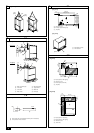
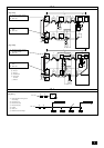
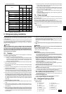
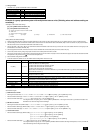
[Fig. 8.2.1]
A: BC controller (standard)
B: BC controller (main)
C: BC controller (sub)
D: indoor unit (06 ~ 54)
E: indoor unit (72, 96)
A
D
E
D
D
D
No.2
No.1
No.3 No.4
No.5
a
b
c
e
A
B
d
B
C
C
D
D
D
D
D
E
D
No.2
No.1
No.3 No.4
No.5 No.6
No.7
a
b
c
d
e
g
f
A
B
C
D
a, b, c, d, e, f, g (Unit: mm [in])
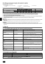
Ô Model number
06,08,12,15,18
24,27,30,36,48,54
72
96
‰ Liquid line
ø6.35 [1/4]
ø9.52 [3/8]
ø9.52 [3/8]
ø9.52 [3/8]
Ï Gas line
ø12.7 [1/2]
ø15.88 [5/8]
ø19.05 [3/4]
ø22.2 [7/8]
C, D (Unit: mm [in])
~ 72
73 ~ 108
109 ~ 126
Ì High press.
gas pipe
ø15.88 [5/8]
ø19.05 [3/4]
ø19.05 [3/4]
¬ Liquid pipe
ø9.52 [3/8]
ø12.7 [1/2]
ø12.7 [1/2]
Ó Low press.
gas pipe
ø19.05 [3/4]
ø22.2 [7/8]
ø28.58 [1-1/8]
B (Unit: mm [in])
Î Total capacity of indoor units
~ 54
55 ~ 72
‰ Liquid line
ø9.52 [3/8]
ø9.52 [3/8]
Ï Gas line
ø15.88 [5/8]
ø19.05 [3/4]
A (Unit: mm [in])
Å Heat source model
P72
P96
ı High press. side
ø15.88 [5/8]
ø19.05 [3/4]
Ç Low press. side
ø19.05 [3/4]
ø22.2 [7/8]
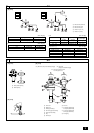
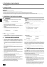
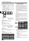
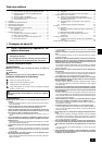
[Fig. 9.2.2]
9.2
9
[Fig. 9.2.1]
A
B
1
3
<A> [Ball valve (Low press. side/flanged type)] <B> [Ball valve
(High press. side/flared type)]
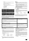
[Fig. 9.2.3]
A: Close-packed packing
B: Hollow packing
<C> This figure shows the valve
in the fully open state.
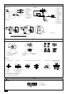
A: Valve stem
B: Stopper pin
C: Packing (Accessory)
D: Connecting pipe (Accessory)
E: Open (Operate slowly)
F: Cap
G: Service port
H: Flare nut
I: ø15.88 [5/8] (PQRY-P72)
ø19.05 [3/4] (PQRY-P96)
J: ø19.05 [3/4] (PQRY-P72)
ø22.2 [7/8] (PQRY-P96)
K: Field piping
I
E
OS
SO
K
J
H
G
F
E
D
C
B
A