


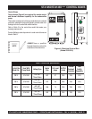

ST-4125D/ST-6125D SUBMERSIBLE PUMPS — OPERATION AND PARTS MANUAL — REV. #1 (06/12/08) — PAGE 17
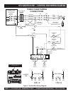
ST-4125D/ST-6125D — 3-PHASE POWER INSTALLATION
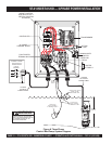
3-PHASE POWER INSTALLATION (OUTPUT TO PUMP)
1. The three phase
output
power cord should have four wires.
Each wire is color coded. The colors are RED, WHITE,
BLACK and GREEN.
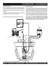
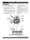
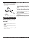
2. Remove the 3-phase AC output power connector housing
on the control box, then route the three phase output power
cable through the cable gland on the control box. Attach
the wires to the AC terminal blocks on the
overload relay
as indicated by Figure 8.
3-PHASE POWER CORD (INPUT TO BOX) INSTALLATION
1. The three phase
input
power cord should have four wires.
Each wire is color coded. The colors are RED, WHITE,
BLACK and GREEN.
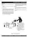
2. Remove the 3-phase AC input connector housing from the
control box, then route the three phase input power cable
through the cable gland on the control box. Attach the
wires to the AC terminal block inside the control box as
indicated by Table 5 and Figure 8.
It is recommended that the power being supplied to the control
box
ALWAYS
be connected to a
circuit breaker
or a
quick
disconnect
switch. This safety feature allows for quick removal
of power from the control box in the event of an emergen
cy.
4. Connect the other end of the 3-phase input power cord to
the voltage source. Remember to provide a means of
disconnecting the power from the control box (circuit breaker
or quick disconnect switch). Also make sure to provide a
good earth ground to the control box.
3. Tighten the connector housing to ensure a tight fit between
the power cord and the connector body. This will prevent
the cable from pulling out of the terminal block and also
prevent moisture from entering the control box.
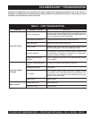
SNOITCENNOCREWOPTUPNICAESAHP-3.5ELBAT S
ROLOCERIWELBAC#KCOLBLANIMRETCA
DER1L
ETIHW2L
KCALB3L
NEERGDNUORG
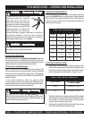
Electrical connections to the power
source should only be performed by
a
licensed electrician
or qualified
personnel.
NOTE