


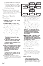

Startup / Checkout
If the burner or control fails any of the
following tests, recheck control wiring. If
the burner or control still fails any tests,
replace the control.
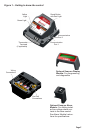
Starting the System
Open the shut-off valves in the
supply line from the oil tank.
Close the disconnect switch to
supply power to the burner.
Adjust the thermostat or boiler
control to call for heat.
If the pump has not been primed,
refer to “Priming the Pump” in
the “Operation” section of this
manual.
Monitor burner operation to ensure
that the burner ignites.
▪
1.
2.
3.
▪
4.
End the call for heat. Verify that the
burner turns off before leaving the
installation site.
Check Safety Features
Safe Start Check
Place a jumper across the cad
cell terminals.
Refer to the steps for “Starting
the System” and have the
system call for heat.
Burner must not start. Verify
that the green light is on
continuously and that the control
remains in Standby mode.
End the call for heat and
remove the cad cell jumper.
Simulate Flame Failure and Ignition
Failure
Refer to the steps for “Starting the
System” and have the system call
for heat.
After ame is established and the
burner igniter turns off, close the
hand valve in the oil supply line.
At ame loss, the control will
enter Recycle mode. Verify that
the green light is ashing. The
control will remain in Recycle for
60 seconds.
After the 60 second recycle period,
the control will try to restart the
system.
After the 15 second lockout time,
the control will lock out the burner
and the reset button will ash.
Verify that the burner motor and
igniter are off and that the burner
oil solenoid valve (if used) is not
energized.
5.
▪
○
1.
2.
3.
4.
○
1.
2.
3.
4.
5.
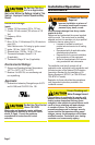
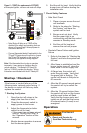
Operation
Reset and Service by
Qualied Technician only.
Fire Hazard
Note: Motor-off delay on a 7505P will be
disabled if the safety and operating limits as
shown in Figures 5 and 9 interrupt power to
the control terminal L1.
Connect thermostat leads (if applicable) to the
TR and TW terminals on the control or jumper
the TR and TW terminals on the control as
directed by the appliance wiring diagram.
Note: If the thermostat short cycles or operates
improperly, it may require an isolation relay for
proper operation. The Beckett A/C Ready Kit
(part no. 51950U) provides this function. Wiring
instructions are included with the A/C Ready Kit.
○
○
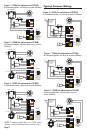
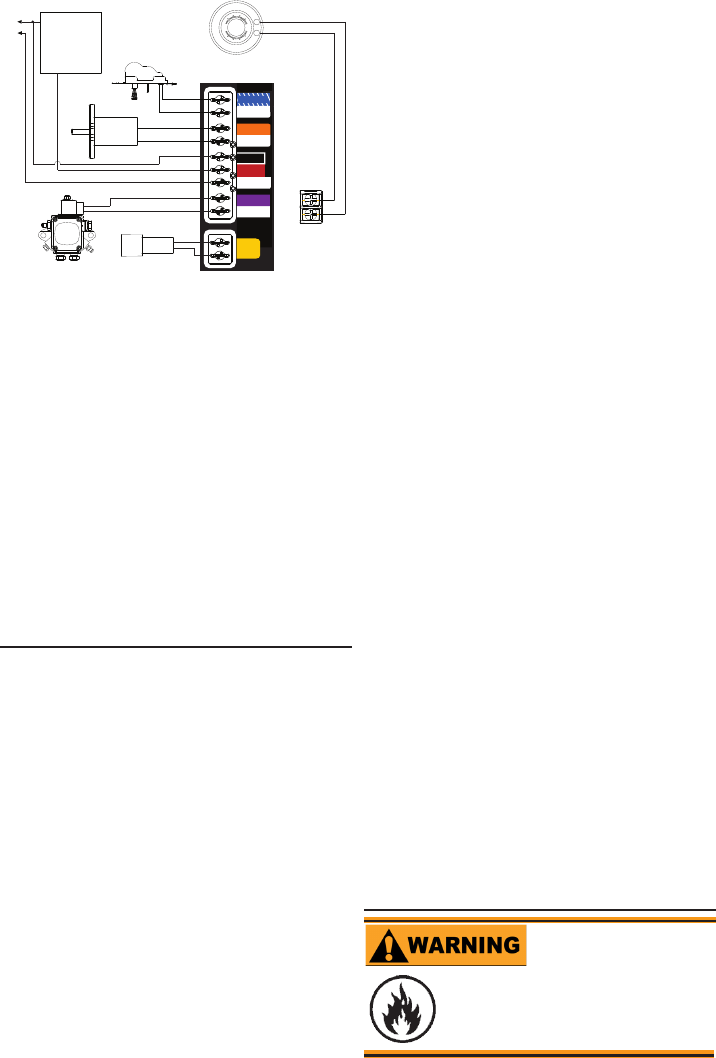
Figure 9 – 7505P (for replacement of R7184P)
● Interrupted ignition, valve-on and motor-off delays
SAFETY AND
OPERATING
LIMITS
LIMIT
L1
L2 (VLV)
VALVE
L2
MOTOR
L2 (MTR)
L2 (IGN)
IGNITER
CAD
CELL
MOTOR
IGNITER
W
R
80
70
60
50
50
70
80
60
OIL VALVE
CAD CELL
THERMOSTAT
TR
TW
TR-TW
JUMPER
TR-TW TERMINALS
LOCATED ON OPPOSITE
SIDE OF CONTROL
L1
L2
TR-TW Terminals
Located on
opposite side of
Control
Page 6