


The control can malfunction if it gets wet,
leading to accumulation of oil or explosive oil
vapors.
Never install where water can ood, drip or
condense on the control.
Never use a control that has been wet
- replace it.
Can cause severe injury, death, or
property damage.
Fire or Explosion
Hazard
Connect the wire from the R
H
or R terminal on
the thermostat to the TR terminal on the control
(if applicable).
Connect the wire from the W terminal on the
thermostat to the TW terminal on the control (if
applicable).
NOTICE
Some Thermostats Are Polarity
Sensitive. Reversed polarity could cause erratic
cycling of the burner control.
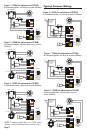
Typical Boiler Wiring:
Incorrect Wiring Will
Result in Improper
GeniSys wiring label colors may not match the
wire colors of the burner or other manufactur-
ers’ controls.
The GeniSys Control should be wired accord-
ing to the appliance manufacturer’s instruc-
tions.
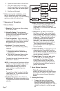
Control Operation
Follow the appliance manufacturer’s wiring
diagrams and note all required safety controls.
Typical safety controls include high
temperature or pressure limits, low water
cutoffs, pressure relief valves and blocked ue
sensing switches.
Verify all limit and safety controls are installed
and functioning correctly, as specied by the
manufacturer, applicable safety standards,
codes and all authorities having jurisdiction.
Ensure that the appliance is free of oil and oil
vapor before starting or resetting the burner.
All heating appliances must have HIGH
LIMIT protection to interrupt electrical
power and shutdown the burner if
Explosion, Fire, Scald,
and Burn Hazard
operating or safety controls fail and cause a
runaway condition.
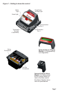
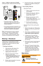
Mounting:
Mount the control on a 4” x 4” junction box on
the burner, or inside the appliance cabinet.
In replacement applications, mount the
new control in the same location as the old
control. In some replacement applications, it
may be necessary to rotate the control on the
4” x 4” box for best t.
Mounting orientation: any orientation is ac-
ceptable.
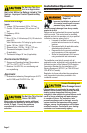
Wiring:
Make sure all appliance wiring complies with
all local codes and ordinances.
Make connections to the control’s terminals
as shown in Figures 2 through 9. Refer to
the label on the underside of the control for
wiring details.
▪
○
○
▪
○
○
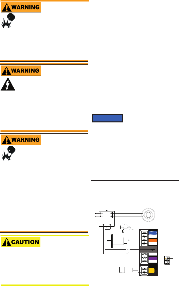
Figure 2 – 7505A (for replacement of R8184G)
● Intermittent ignition, no valve-on delay, no
motor-off delay
Electrical shock can cause severe
personal injury or death.
Electrical Shock Hazard
Disconnect ALL electrical power to the
appliance/burner circuit before installing or
servicing this control.
Provide ground wiring to the appliance, burner
and metal control mounting box.
Perform all wiring in compliance with the
National Electrical Code ANSI/NFPA 70
(Canada CSA C22.1).
LIMIT
L1
L2 (VLV)
VALVE
L2
MOTOR
L2 (MTR)
L2 (IGN)
IGNITER
CAD
CELL
MOTOR
IGNITER
W
R
80
70
60
50
50
70
80
60
LIMIT
CAD CELL
THERMOSTAT
BOILER CONTROL
TR
TW
TR-TW
JUMPER
TR-TW TERMINALS
LOCATED ON OPPOSITE
SIDE OF CONTROL
B2 B1
T
T
L1
L2
L1
L2
TR-TW Terminals
Located on
opposite side of
Control
(If applicable)
Page 4