


75.1035 V1 Feb 2001 Page 6 of 8
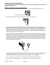
Adjustment of the Detection Distance
Use the procedure listed below to adjust each detector in order to obtain detection 12" to 16" above the floor. The
following adjustments must be made with the detectors in the normal mode (position of J1)
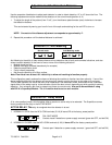
1. To adjust the length of the pattern (from 2’ to 8’), turn the distance potentiometer (cam) clockwise to increase
the detection distance.
This can be tested by waving your hand in front of the optic and watching for the red LED to turn on.
NOTE: One notch of the distance adjustment corresponds to approximately 4".
2. Repeat this procedure until the desired distance is achieved.
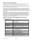
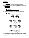
Function J1: Anti-Masking
Normal mode
Anti-Masking mode
Anti-Masking is the ability to help reduce chances of non-detection due to faulty environmental situations, and also
allows constant detection in the event of one or more of the following situations:
•
Module aimed too high
•
Module incorrectly oriented (towards sky for example)
•
Defective amplification chain
•
Faulty infrared transmitter
•
Not enough reflectivity off of floor surface
Note: Floor must have at least 10% reflectivity to allow anti-masking to function properly.
This configuration greatly reduces the chance of allowing the modules to function less than optimally. If one of the
above-stated faults exists, the detector will remain active, thereby causing the door to stay open or to not open.
This fail-safe operation will cause the door to be inoperative in the automatic mode, since there will be a constant
signal either to the safety input or to the activation input of the door control, depending on which module is sensing
detection. If an extremely dark floor is present set jumper to normal mode. Also set to Normal Mode if using
with B.E.A.'s SuperStop Module. The J1 function must be set on each module.
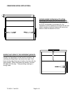
Function J2: Relay Mode
J2 is a two-position jumper, which enables either a passive or active relay to be selected. The SuperScan comes
factory preset with the relay in the ACTIVE MODE.
ACTIVE RELAY: The
relay is energized when the detector is at rest
1. NORMALLY OPEN: Use the NC & COM terminals (5 & 6) & leave JP2 at the factory preset position.
FAIL SAFE MODE
Contact closed if detection or power supply removed (green led OFF, red led ON)
2. NORMALLY CLOSED: Use the NO & COM terminals (4 & 6) & leave JP2 at the factory preset position.
Contact open if detection or power supply removed (green led OFF, red led ON)