


Operations Overview 1-2
B1272M001
BARNETT ENGINEERING LTD. ProTalk Cv2
HARDWARE
INPUTS
8
INPUTS
8
OUTPUTS
POINTS
UP TO 30 INPUTS OR OUTPUTS
GROUP
1
TELEPHONE
PORT
HARDWARE
OUTPUTS
GROUP
6
DIRECTORY
A
DIRECTORY
F
DIALOUT
COMMANDS
CONTROL
COMMANDS
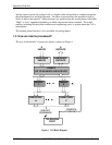
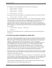
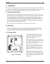
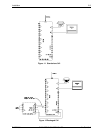
Figure 1 Cv2 Block Diagram
Analog inputs convert the voltage level to a digital value and perform a comparison against
the programmed low and high setpoints. An alarm is present when the measured value is
above or below the setpoint. Alarm messages are spoken using the stored phrase with either
“High” or Low” appended depending on which setpoint has been exceeded. The actual
reading, including decimal place notation and engineering units, is spoken when the Cv2 is
interrogated.
The latching alarm function is also available for analog inputs.
1.3 How are alarms processed?
The way in which the Cv2 processes alarms is shown in Figure 1.