


Installation 2-3
B1272M001 BARNETT ENGINEERING LTD. ProTalk Cv2
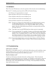
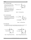
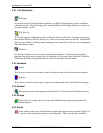
Figure 5 +12 Volt Input Wiring
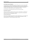
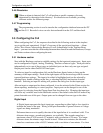
Figure 6 +5 VDC Input Wiring
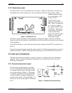
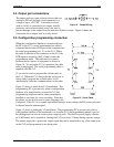
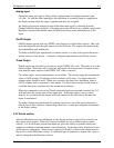
Figure 8 Analog (unfiltered) Input Wiring
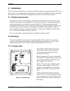
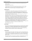
Figure 7 Analog (filtered) Input Wiring
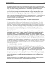
2.3.2 +12 volt alarm signal
The input will accept an alarm signal
that switches between 0 and +12 volts
with the wiring arrangement shown in
Figure 5.
If the signal switches between +12 volts
and an open circuit, as in the case of a
relay contact, the ‘B’ terminal must be
connected to ground to ensure that the
logic level goes to ground when the
voltage is removed.
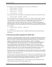
2.3.3 +5 volt alarm signal
Figure 6 shows how an alarm signal that
switches between +5 volts and ground is
wired. If the alarm signal does not have a
true ground level, terminal ‘B’ must be
connected to ground.
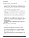
2.3.4 Analog input
For analog signals, either of the wiring configurations shown in Figures 7 and 8 can be used.
The connection shown in Figure 7 will provide additional filtering of the signal.