


Manual 2100-519C
Page 33 of 42
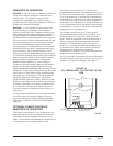
SEQUENCE OF OPERATION
COOLING –
Circuit R-Y makes at thermostat pulling in
compressor contactor, starting the compressor and
outdoor motor. The G (indoor motor) circuit is
automatically completed on any call for cooling
operation or can be energized by manual fan switch on
subbase for constant air circulation.
HEATING –
A 24V solenoid coil on reversing valve
controls heating cycle operation. Two thermostat
options, one allowing “Auto” changeover from cycle to
cycle and the other constantly energizing solenoid coil
during heating season, and thus eliminating pressure
equalization noise except during defrost, are to be used.
On “Auto” option a circuit is completed from R-W1 and
R-Y on each heating “on” cycle, energizing reversing
valve solenoid and pulling in compressor contactor
starting compressor and outdoor motor. R-G also make
starting indoor blower motor. Heat pump heating cycle
now in operation. The second option has no “Auto”
changeover position, but instead energizes the reversing
valve solenoid constantly whenever the system switch on
subbase is placed in “Heat” position, the “B” terminal
being constantly energized from R. A Thermostat
demand for heat completes R-Y circuit, pulling in
compressor contactor starting compressor and outdoor
motor. R-G also make starting indoor blower motor.
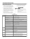
High / Low Pressure control provides protection for the
compressor. In the event system pressures go above 600
PSI or below 15 PSI in either cooling or heating mode,
the compressor will be stopped. This will activate the
red light located in the control panel. The lockout
circuit will hold compressor off line. When the system
problem is corrected, the unit operation can be restored
by turning of the main power supply off and then back
on, or reset the room thermostat. The low pressure
control has a bypass to eliminate nuisance lockout on
cold start up.
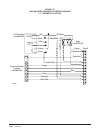
The bypass timer should be set to 120 seconds and this
is to assure there is no nuisance tripping of the low-
pressure control during startup in heating mode under
cold weather conditions. See Defrost Control Board -
Figure 24.
OPTIONAL CLIMATE CONTROLS
SEQUENCE OF OPERATION
The Climate Control Option “A” is an electronic, non-
programmable manual or auto changeover thermostat.
The thermostat may be manually set to heat or cool
mode. The thermostat will maintain the temperature set
on the thermostat in the mode in which it is set.
The Climate Control Option “D” is an electronic,
programmable thermostat. The thermostat can be set in
the heat, cool or automatic mode. When the thermostat
is set in the heat mode, it can heat only to maintain the
temperature set on the thermostat. When the thermostat
is set in the cool mode, it can cool only to maintain the
temperature set on the thermostat. When the thermostat
is set in the automatic mode, the thermostat can change
automatically to the heat or cool modes to maintain the
temperature set on the thermostat.
The Climate Control Option “H” is an electronic,
programmable thermostat and a CO
2
controller. The
thermostat can be set in the heat, cool or automatic
mode. When the thermostat is set in the heat mode, it
can heat only to maintain the temperature set on the
thermostat. When the thermostat is set in the cool
mode, it can cool only to maintain the temperature set
on the thermostat. When the thermostat is set in the
automatic mode, the thermostat can change
automatically to the heat or cool modes to maintain the
temperature set on the thermostat.
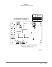
The CO
2
controller will energize the vent option and the
ID blower when the room CO
2
levels rise over set level.
Default CO
2
set point is 1000 ppm. See Figure 23.
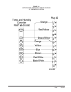
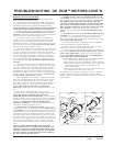
"SW1" SET TO ON "OUT" SET TO 20-100%
"SW2" SET TO ON
OFF
ON
ON
OFF
0-100%
20-100%
VOLTAGE
CURRENT
SW2SW1OUT AN
"AN" SET TO VOLTAGE
MIS-2667
FIGURE 23
CO
2
CONTROLLER – FACTORY SET TO 1000
PPM