


Manual 2100-519C
Page 19 of 42
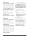
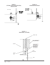
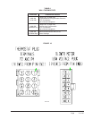
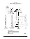
The standard Climate Control Option X is a remote
thermostat connection terminal block. See Figure 17A
for wiring diagram. Compatible thermostats are listed
in Table 4. See Fig. 17B for Remote CO
2
Sensor
Connection.
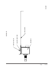
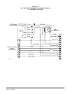
The Climate Control Option A is an electronic, non-
programmable manual or auto changeover thermostat.
The subbase of the thermostat is factory wired to the
front panel of the unit. See Figure 18 for wiring
diagram. Compatible for use with Bard CS2000A*
Controller and Energy Recovery Ventilator.
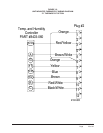
The Climate Control Option D is an electronic,
programmable thermostat. The subbase of the
thermostat is factory wired to the front panel of the unit.
See Figure 19 for wiring diagram. Compatible for use
with Energy Recovery Ventilator or Economizer.
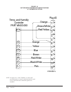
The Climate Control Option H is an electronic,
programmable thermostat and a CO
2
controller. The
subbase of the thermostat and CO
2
controller are factory
wired to the front panel of the unit. See Figure 20 for
wiring diagram.
NOTE: On option X or A the CS2000A* (or other field
provided means to control ventilation) must be
used if any of the motorized ventilation options
are installed.
WIRING – MAIN POWER
Refer to the unit rating plate and/or Table 2 for wire
sizing information and maximum fuse or “HACR Type”
circuit breaker size. Each unit is marked with a
“Minimum Circuit Ampacity”. This means that the
field wiring used must be sized to carry that amount of
current. Depending on the installed KW of electric
heat, there may be two field power circuits required. If
this is the case, the unit serial plate will so indicate. All
models are suitable only for connection with copper
wire. Each unit and/or wiring diagram will be marked
“Use Copper Conductors Only”. These instructions
MUST BE adhered to. Refer to the National Electrical
Code (NEC) for complete current carrying capacity data
on the various insulation grades of wiring material. All
wiring must conform to NEC and all local codes.
The electrical data lists fuse and wire sizes (75°C
copper) for all models, including the most commonly
used heater sizes. Also shown are the number of field
power circuits required for the various models with
heaters.
The unit rating plate lists a “Maximum Time Delay
Relay Fuse” or “HACR Type” circuit breaker that is to
be used with the equipment. The correct size must be
used for proper circuit protection, and also to assure that
there will be no nuisance tripping due to the momentary
high starting current of the compressor motor.
The disconnect access door on this unit may be locked
to prevent unauthorized access to the disconnect.
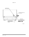
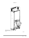
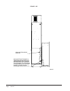
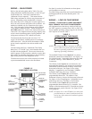
FIGURE 15
COMPONENT LOCATION
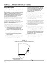
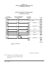
TABLE 3
OPERATING VOLTAGE RANGE
NOTE: The voltage should be measured at the field
power connection point in the unit and while
the unit is operating at full load (maximum
amperage operating condition).
PATEGNAR
V042612–352
V802781–022
See Start Up section for information on three phase
scroll compressor start-ups.
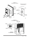
The field wiring connections are located behind the top
and hinged panel in the circuit breaker panel. See
Figure 15.
WIRING – LOW VOLTAGE WIRING
230/208V, 1 PHASE AND 3 PHASE EQUIPMENT
DUAL PRIMARY VOLTAGE TRANSFORMERS.
All Equipment leaves the factory wired on 240V tap.
For 208V operation, reconnect from 240V to 208V tap.
The acceptable operating voltage range for the 240 and
208V taps are as noted in Table 3.
DEHUMIDIFICATION
CONTROL
(OPTIONAL)
UNIT
MOUNTED
THERMOSTAT
LOCATION
ELECTRIC
HEATERS
CIRCUIT
BREAKER PANEL
& CONTROLS
I
NDOOR
BLOWER
REMOTE
THERMOSTAT
TERMINAL
BLOCK
SIDE FIELD WIRE
ENTRANCE
LOWER
CONTROL
PANEL