


Manual 2100-467
Page 4 of 23
GENERAL INSTRUCTIONS
IMPORTANT
The equipment covered in this manual is to be installed
by trained, experienced service and installation
technicians. All duct work, supply and return ducts,
must be properly sized for the design air flow
requirement of the equipment. ACCA is an excellent
guide to proper sizing. All duct work or portions thereof
not in the conditioned space should be properly
insulated in order to both conserve energy and prevent
condensation or moisture damage.
SHIPPING DAMAGE
Upon receipt of equipment, the carton should be
checked for external signs of shipping damage. If
damage is found, the receiving party must contact the
last carrier immediately, preferably in writing,
requesting inspection by the carrier’s agent.
GENERAL
The refrigerant system is completely assembled and
charged. All internal wiring is complete.
The unit is designed for use with or without duct work.
Flanges are provided for attaching the supply and return
ducts.
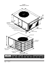
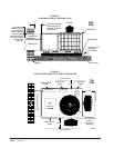
These instructions explain the recommended method to
install the air cooled self-contained unit and the
electrical wiring connections to the unit.
These instructions and any instructions packaged with
any separate equipment required to make up the entire
system should be carefully read before beginning the
installation. Note particularly “Starting Procedure” and
any tags and/or labels attached to the equipment.
While these instructions are intended as a general
recommended guide, they do not supersede any national
and/or local codes in any way. Authorities having
jurisdiction should be consulted before the installation is
made.
FIELD INSTALLED HEATER PACKAGES
(OPTIONAL)
These packaged air conditioners are manufactured
without supplementary electric heaters. Supplementary
heaters are available for simple, fast field installation.
A separate power circuit is required for the
supplementary heaters.
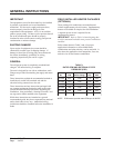
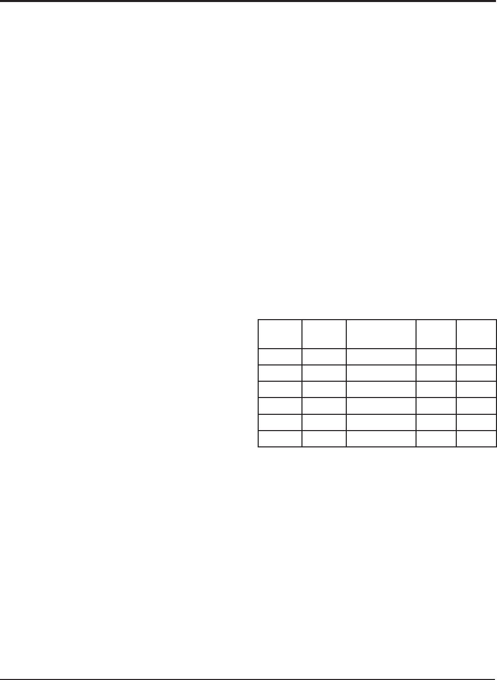
IMPORTANT: Refer to Table 1 when designing duct
work for maximum available static pressure with heater
installed.
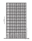
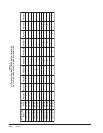
Refer to data shown in Table 3 and 4 for proper
application information on all available heater
combinations and what units they can be used with. It
also shows the applicable circuit ampacities, fuse size,
and wire size for each heater combination.
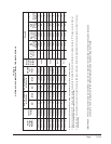
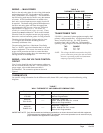
TABLE 1
RATED CFM AND EXTERNAL STATIC
PRESSURE (ESP)
NOTE: ECM motors provide rated CFM up to 0.50 ESP
ledoM
.oN
detaR
MFC
dednemmoceR
egnaRwolfriA
detaR
PSE
.xaM
PSE
14231AP
008
etoN
81.005.0
10331AP0001
etoN
32.005.0
16331AP
0011
etoN
32.005.0
12431AP
0041
etoN
32.005.0
18431AP
0551
etoN
82.005.0
10631AP
0561
etoN
82.005.0