


Manual 2100-467
Page 16 of 23
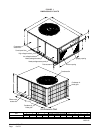
THREE PHASE SCROLL COMPRESSOR
START UP INFORMATION
(PA1336, 42, 48 and 60 Models)
Scroll compressors, like several other types of
compressors, will only compress in one rotational
direction. Direction of rotation is not an issue with
single phase compressors since they will always start
and run in the proper direction.
However, three phase compressors will rotate in either
direction depending upon phasing of the power. Since
there is a 50-50 chance of connecting power in such a
way as to cause rotation in the reverse direction,
verification of proper rotation must be made.
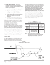
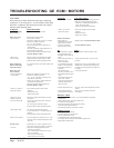
Verification of proper rotation direction is made by
observing that suction pressure drops and discharge
pressure rises when the compressor is energized.
Reverse rotation also results in an elevated sound level
over that with correct rotation, as well as, substantially
reduced current draw compared to tabulated values.
Verification of proper rotation must be made at the
time the equipment is put into service. If improper
rotation is corrected at this time there will be no
negative impact on the durability of the compressor.
However, reverse operation for over one hour may have
a negative impact on the bearing due to oil pump out.
NOTE: If compressor is allowed to run in reverse
rotation for several minutes the compressor’s
internal protector will trip.
All three phase scroll compressors are wired identically
internally. As a result, once the correct phasing is
determined for a specific system or installation,
connecting properly phased power leads to the same
Fusite terminals should maintain proper rotation
direction.
The direction of rotation of the motor may be changed
by reversing any two line connections to the unit.
SEQUENCE OF OPERATION
BLOWER ONLY
– When the “Fan” switch on the
room thermostat is placed in the “On” position (circuit
R-G makes), the blower will energize and run until the
“Fan” switch is placed back into the “Auto” position.
This will allow for constant air circulation at a lower
airflow during times when the unit is not in operation
for cooling or heating.
COOLING
– On a call for cooling from the room
thermostat (circuit R-Y makes), the blower will energize
(circuit R-G is automatic when R-Y makes) as well as
the compressor, and outdoor fan motor. Note that if the
“Fan” switch on the room thermostat is in the “On”
position and the blower is already in operation, then the
motor will ramp up to the required speed for cooling.
HEATING (1st Stage)
– On a call for heating from
the room thermostat (circuit R-W1 makes), the blower
will energize (circuit R-G is automatic when R-W1
makes). This will place the system into heating
operation to maintain the thermostat set temperature.
Note that if the “Fan” switch on the room thermostat is
in the “On” position and the blower is already in
operation, then the motor will ramp up to the required
speed for heating.
HEATING (2nd Stage)
– If the operation of the 1st
Stage electric heaters will not maintain the set room
temperature, then the thermostat will call for additional
heat to help maintain the set temperature. On a call for
second stage heating from the room thermostat (circuit
R-W2 makes), additional electric heaters will be
energized if installed.
INDOOR BLOWER MOTOR
Some models feature a variable speed (ECM) motor
providing high efficiency, low sound levels and soft
start capabilities. The motor is self adjusting to provide
the proper air flow rate at duct static pressures up to
0.50" WC without user adjustment or wiring changes.
On command from the wall thermostat the motor will
start slowly and ramp up to full speed over a period of
10- 15 seconds.
When the thermostat is satisfied the blower will operate
for approximately 1 minute, and then slow down and
stop.
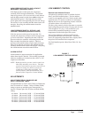
COMPRESSOR CONTROL MODULE
The compressor control is an anti-short cycle/lockout
timer with high and low pressure switch monitoring and
alarm output.
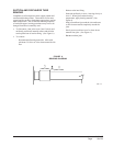
ADJUSTABLE DELAY-ON-MAKE AND BREAK
TIMER
On a call for compressor operation the delay-on-make
period begins which will be 10% of the delay-on-break
setting. When the delay-on-make is complete and the
high pressure switch (and low pressure switch if
employed) is closed, the compressor contactor is
energized. Upon shutdown the delay-on-break timer
starts and prevents restart until the delay-on-break and
delay-on-make periods have expired.
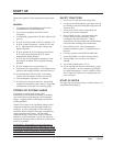
START UP AND OPERATION