


Manual 2100-324
Page 12
START UP AND OPERATION
THREE PHASE SCROLL COMPRESSOR
START UP INFORMATION
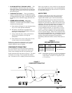
Scroll compressors, like several other types of
compressors, will only compress in one rotational
direction. Direction of rotation is not an issue with single
phase compressors since they will always start and run in
the proper direction.
However, three phase compressors will rotate in either
direction depending upon phasing of the power. Since
there is a 50-50 chance of connecting power in such a way
as to cause rotation in the reverse direction, verification of
proper rotation must be made. Verification of proper
rotation direction is made by observing that suction
pressure drops and discharge pressure rises when the
compressor is energized. Reverse rotation also results in
an elevated sound level over that with correct rotation, as
well as, substantially reduced current draw compared to
tabulated values.
Verification of proper rotation must be made at the time
the equipment is put into service. If improper rotation is
corrected at this time there will be no negative impact on
the durability of the compressor. However, reverse
operation for over one hour may have a negative impact on
the bearing due to oil pump out.
NOTE: If compressor is allowed to run in reverse
rotation for several minutes the compressor’s
internal protector will trip.
All three phase ZR*3 compressors are wired identically
internally. As a result, once the correct phasing is
determined for a specific system or installation, connecting
properly phased power leads to the same Fusite terminals
should maintain proper rotation direction.
The direction of rotation of the motor may be changed by
reversing any two line connections to the unit.
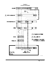
SEQUENCE OF OPERATION
COOLING
– Circuit R-Y makes at thermostat pulling in
compressor contactor starting the compressor and outdoor
motor. The G (indoor motor) circuit is automatically
completed on any call for cooling operation, or can be
energized by manual fan switch on subbase for constant air
circulation.
HEATING
– A circuit R-W1 is completed on each
heating cycle energizing electric heat if so equipped.
START UP NOTES
For improved start up performance, wash the indoor coil
with dishwasher detergent
COMPRESSOR CONTROL MODULE
The compressor control is an anti-short cycle/lockout timer
with high and low pressure switch monitoring and alarm
output.
ADJUSTABLE DELAY-ON-MAKE AND BREAK
TIMER
On a call for compressor operation the delay-on-make
period begins which will be 10% of the delay-on-break
setting. When the delay-on-make is complete and the high
pressure switch (and low pressure switch if employed) is
closed, the compressor contactor is energized. Upon
shutdown the delay-on-break timer starts and prevents
restart until the delay-on-break and delay-on-make periods
have expired.
HIGH PRESSURE SWITCH AND LOCKOUT
SEQUENCE (Standard Feature)
If the high pressure switch opens, the compressor
contactor will de-energize immediately. The lockout timer
will go into a soft lockout and stay in soft lockout until the
high pressure switch closes and the delay-on-make time
has expired. If the high pressure switch opens again in this
same operating cycle the unit will go into manual lockout
condition and the alarm circuit will energize. Recycling
the wall thermostat resets the manual lockout.
LOW PRESSURE SWITCH, BYPASS, AND
LOCKOUT SEQUENCE
NOTE: The low pressure switch is an optional control
and the bypass and lockout sequence are part of
the standard compressor control module.
If the low pressure switch opens for more that 120
seconds, the compressor contactor will de-energize and go
into a soft lockout. Regardless the state of the low
pressure switch, the contactor will reenergize after the
delay-on-make time delay has expired. If the low pressure
switch remains open or opens again for longer than 120
seconds the unit will go into manual lockout condition and
the alarm circuit will energize. Recycling the wall
thermostat resets the manual lockout.