


Manual 2100-324
Page 10
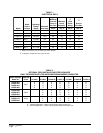
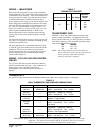
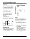
TABLE 7
THERMOSTAT WIRE SIZE
AVremrofsnarTALFeguaGeriW
mumixaM
ecnatsiD
teeFnI
553.2
02
81
61
41
21
54
06
001
061
052
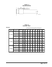
TABLE 8
WALL THERMOSTAT AND SUBBASE COMBINATIONS
tatsomrehTesabbuSserutaeFetanimoderP
200-3048
1113F78T
300-4048
0221A935Q
yrucreM,loocegats1,taehegats1
otua-no:naFlooc-ffo-taeH:metsyS
140-3048
9941C4308T
——
yrucreM,loocegats1,taehegats1
otua-no:naFlooc-ffo-taeH:metsyS
940-3048
083-39F1
——
loocegats2,taehegats2
elbammargorPcinortcelE
340-3048
002MC
——
yrucreM,loocegats1,taehegats1
otua-no:naFlooc-ffo-taeH:metsyS
noitcApanS
840-3048
3131C0048T
——
yrucreM,loocegats1,taehegats1
otua-no:naFlooc-ffo-taeH:metsyS
elbammargorP-noNcinortcelE
910-3048
0671C478T
210-4048
1001A476Q
yrucreM,loocegats1,taehegats2
otua-no:naFlooc-otua-taeh:metsyS
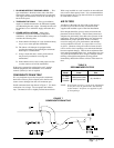
TRANSFORMER TAPS
230/208V, 1 phase and 3 phase equipment employ dual
primary voltage transformers. All equipment leaves the
factory wired on 240V tap. For 208V operation, reconnect
from 240V to 208V tap. The acceptable operating voltage
range for the 240 and 208V taps are:
TAP RANGE
240 253 – 216
208 220 – 187
NOTE: The voltage should be measured at the field
power connection point in the unit and while the
unit is operating at full load (maximum
amperage operating condition).
WIRING – MAIN POWER
Refer to the unit rating plate for wire sizing information
and maximum fuse size. Each outdoor unit is marked with
a “Minimum Circuit Ampacity”. This means that the field
wiring used must be sized to carry that amount of current.
If field installed heaters are added to the basic unit, a
second separate power supply circuit will be required. The
heater rating plate located adjacent to the basic unit rating
plate will show the appropriate circuit ampacity fuse size,
etc. (Also see “Electrical Data” on pages 2 and 3.) All
models are suitable for connection with copper wire only.
These instructions must be adhered to. Refer to the
National Electrical Code for complete current carrying
capacity data on the various insulation grades of wiring
material.
The electrical specifications on page 2 and 3 lists fuse and
wire sizes (75°F copper) for all models including the most
commonly used heater sizes.
The unit rating plate lists a “Maximum Time Delay Fuse”
or “HACR” type circuit breaker that is to be used with the
equipment. The correct size must be used for proper
circuit protection and also to assure that there will be no
nuisance tripping due to the momentary high starting
current of the compressor.
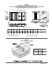
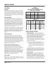
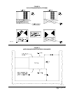
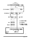
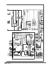
WIRING – 24V LOW VOLTAGE CONTROL
CIRCUIT
Five (5) wires should be run from thermostat subbase to
the 24V terminal board in the unit. A five conductor, 18
gauge copper, color-coded thermostat cable is
recommended. The connection points are shown in
Figure 8.
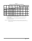
THERMOSTATS
See specific wiring information for the different models, heater KWs, and voltages on pages 14 through 17.
IMPORTANT NOTE: Only the thermostat and subbase combinations as shown above will work with this
equipment. The thermostat and subbase MUST be matched, and correct operation
can be assured only by proper selection and application of these parts.