


Manual 2100-517
Page 3 of 11
GENERAL
The pump module kit should only be installed by trained
technicians. These instructions serve as a guide to the
technician installing the pump module kit. They are not
intended as a step-by-step procedure with which the
mechanically inclined owner can install the unit.
DESCRIPTION
The system is designed to heat domestic water using heat
recovered from a water source unit’s hot discharge gas.
LOCATION
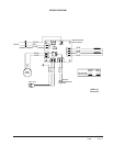
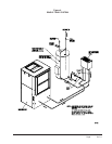
There are two options for the mounting location of the
GVDM-26 Domestic Hot Water Desuperheater Module.
First, there are pre-punched mounting holes for it on the
side of the geothermal heat pump beneath the filter rack.
Factory supplied in the kit are interconnect tubes that
connect the pump module to the water source unit (See
Figure 1).
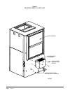
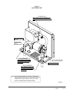
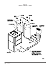
The second is to locate the GVDM-26 on a wall adjacent
to the geothermal unit or storage tank/water heater. (See
Figures 3 and 4.)
Because of potential damage from freezing or
condensation, the unit must be located in a conditioned
space, therefore the GVDM-26 must be installed indoors.
Locate the storage tank as close to the geothermal heat
pump and pump module as the installation permits.
Keep in mind that water lines should be a maximum of
25 feet long measured one way. Also, the vertical lift
should not exceed 20 feet. This is to keep pressure and
heat losses to a minimum.
ELECTRICAL CONNECTION
The GVDM-26 is equipped with a standard 115V 3-prong
plug. The unit is rated at .9 amps and can normally be
plugged into any convenient electrical outlet.
NOTE: Make sure outlet is grounded, and that the
circuit will handle the added load. If any
concerns in this regard you should run a
separate grounded circuit to the main panel.
SOLDERING TUBING
NOTE: The “inlet” and “outlet” thermistors should be
removed from the tubes prior to soldering/
brazing operation so they are not damaged.
They are clipped onto the “DSH COIL INLET”
and from “DSH OUTLET” tubes of the GVDM-
26 Module. Once soldering operations are
complete, and the tubes have cooled, reattach
the sensors and wrap with provided insulation.
INSTALLATION PROCEDURE – GENERAL
Before beginning the installation, turn off all power
supplies to the water heater and unit, and shut off the
main water supply line.
TWO TANK – In order to realize the maximum energy
savings from the heat recovery system, it is
recommended that a second water storage tank be
installed in addition to the main hot water heater. Fossil
fuel fired water heaters must be a two-tank installation.
Tanks specifically intended for hot water storage are
available from water heater manufacturers (solar hot
water storage tanks). A well insulated electric water
heater without the electric heating elements will also
make a suitable storage tank.
The size of storage tank should be as large as space and
economy permit but in no event should it be less than
one-half of the daily water requirements for the
occupants. As a guide in estimating the daily family
water requirements, The Department of Energy
recommends a figure of 16.07 gallons of hot water per
day per individual. For example, a family of four would
require 64.3 gallons per day (4 x 16.07).
ONE TANK – The single hot water tank may be a new
hot water heater (sized to 100% of daily water
requirements) or the existing water heater in the case of a
retrofit installation. The existing water heater should be
drained and flushed to remove all loose sediment. This
sediment could damage the circulating pump. The
bottom heating element should be disconnected.
NOTE: Make sure water heater thermostats are set
below 125° on One Tank Unit.
WATER PIPING – All water piping must adhere to all
state and local codes. Refer to piping diagrams for
recommended one and two tank installations. Piping
connections are 1/2 inch nominal copper plumbing.
A cleanable “Y” type strainer should also be included to
collect any sediment.
WARNING
Never alter or plug factory installed pressure
relief valve on water heater or auxiliary tank.